Inertial temp. control system and method

A technology of temperature control and temperature controller, applied in the field of inertial temperature control system, can solve problems such as unwanted

Inactive Publication Date: 2002-10-02
ASML US LLC
View PDF0 Cites 12 Cited by
  • Summary
  • Abstract
  • Description
  • Claims
  • Application Information

AI Technical Summary

Problems solved by technology

[0008] The time delay or hysteresis at the start of the ramp, the overshoot of the desired set point and the temperature oscillations relative to the set point, these are in figure 1 The characteristics shown in , associated with prior art control methods, are undesirable in many applications where stable and precise temperature control is required

Method used


Image

  • Inertial temp. control system and method
  • Inertial temp. control system and method
  • Inertial temp. control system and method

Examples


Embodiment Construction

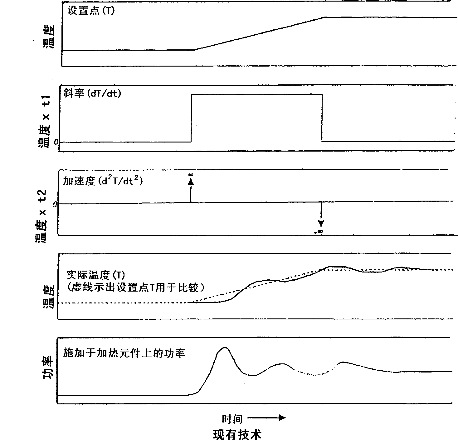
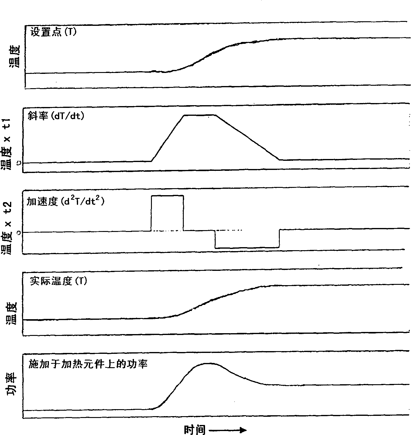
[0022] The idea involved in the inertial temperature control of the present invention has to do with how the temperature set point is managed. In prior art temperature control methods applied in the semiconductor industry, objects or bodies, such as semiconductor wafers, typically have a temperature slope in a linear fashion. The actual temperature of the body cannot match this linear temperature slope, so it lags at the beginning and overshoots at the end. In contrast, the present invention provides a curve of temperature set point versus time that more closely matches a curve that real objects can follow. In this way, the present invention calculates the "inertial" nature of temperature change, and controls the set point to allow the actual temperature of the body to follow the set point temperature more closely, thereby reducing overshoot, and at the same time, compared to the prior art straight line slope method. Achieve temperature stability faster.

[0023] Heat applie...


PUM


Abstract

The present invention provides an inertial temperature control system and method for varying the temperature of a body between two temperatures to smoothly reach an end temperature with substantially no temperature overshoot or oscillations. A setpoint temperature is input to the temperature control algorithm, which accelerates or decelerates at a physically achievable rate.

Description

[0001] Priority data: [0002] This application claims priority from the earlier application, Serial No. 60 / 266,926, filed February 6, 2001, the disclosure of which is incorporated herein by reference in its entirety. Technical field: [0003] The present invention relates to a temperature control system and method for changing from one set point temperature to another. More particularly, the present invention relates to inertial temperature control systems and methods for use in manufacturing processes, such as, but not limited to, semiconductor manufacturing processes and equipment. Background technique: [0004] Temperature control systems and methods play an important role in many manufacturing processes. In the prior art of the method of controlling the temperature in the production process, a temperature algorithm such as a proportional-integral-derivative algorithm (PID) or fuzzy logic is used. The PID algorithm is well known in control theory and uses the differenc...

Claims


Application Information

Patent Timeline
Patent Type & Authority Applications(China)
IPC IPC(8): G05B11/42G05D23/19H01L21/00H05B1/02
CPCG05D23/1935H01L21/67248H05B1/0233G05B11/42
Inventor 艾伦·L.·斯塔纳
Owner ASML US LLC
Why Eureka
Try Eureka