Miniature silicon dridge type heat convection acceleration sensor

A technology of acceleration sensor and temperature sensor, which is applied in the field of sensors, can solve the problems of nonlinear output signal, large structure size, and low response frequency, and achieve the effect of small size, low cost, and good performance

Inactive Publication Date: 2002-10-09
TSINGHUA UNIV
View PDF1 Cites 18 Cited by
  • Summary
  • Abstract
  • Description
  • Claims
  • Application Information

AI Technical Summary

Problems solved by technology

The shortcomings of the acceleration sensor are: 1) large structure size an

Method used


Image

  • Miniature silicon dridge type heat convection acceleration sensor
  • Miniature silicon dridge type heat convection acceleration sensor
  • Miniature silicon dridge type heat convection acceleration sensor

Examples


Embodiment Construction

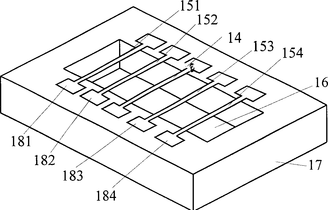
[0025] The embodiment of a miniature silicon bridge type thermal convection acceleration sensor designed in the present invention is described in detail as follows with reference to the accompanying drawings:

[0026] The structure of this embodiment is as image 3 As shown, it is mainly composed of a silicon base 17, a cavity 16 for providing natural convection space, a heating wire 14, a temperature sensor 151, 152, 153, 154 and their corresponding electrical contact pieces 181, 182, 183, and 184. The height of the silicon base 17 is 500 μm, the length of the cavity 16 is 3000 μm, the width is 910 μm, and the height is 250 μm. The heating wire 14 has a width of 80 μm and a height of 2 μm. The temperature sensor 15 has a width of 30 μm and a height of 2 μm. A pair of temperature sensors 152 and 153 close to the heating wire are symmetrically arranged on both sides of the heating wire, and their distance is 750 μm. Another pair of sensors 151 and 154 are also symmetrically arrange...


PUM


Abstract

A miniature silicon bridge type acceleration sensor based on heat convection principle is composed of a sealed cavity, a heating wire in the center of said cavity, two pairs of temp sensors symmetricabout said heating wire and bridge-type temp measuring circuit composed of said temp sensors. Its advantages are high range and impact resistance, small size, low cost, and high linearity, sensitivity and response frequency.

Description

Technical field [0001] The invention belongs to the technical field of sensors, and particularly relates to the structural design of a thermal convection accelerometer suitable for silicon micro-processing. Background technique [0002] Acceleration sensors have broad application prospects in transportation (cars, airplanes, ships), civilian products (cameras, toys, mice), industrial control and robotics, and military (missiles, precision guided weapons, satellites) and other fields. The development of a new type of accelerometer with smaller size, better performance, higher reliability, and lower price is a goal that people have been pursuing. The general characteristic of accelerometers currently in use is the need to inspect masses. The existence of the mass block makes the sensor have a narrow measuring range, weak impact resistance and low reliability, and also makes the structure larger and higher cost. In addition, the detection of mass movement also has problems of one ki...

Claims


Application Information

Patent Timeline
IPC IPC(8): G01P15/00
Inventor 李志信罗小兵过增元胡桅林
Owner TSINGHUA UNIV
Why Eureka
Try Eureka