Apparatus for winding long materials
A winding device and object technology, applied in the direction of winding strips, transportation and packaging, and conveying filamentous materials, etc., can solve the problems of unsteady winding and large displacement of the regulator, and achieve simple structure, loose winding The effect of reducing and preventing overcurrent or overvoltage
- Summary
- Abstract
- Description
- Claims
- Application Information
AI Technical Summary
Problems solved by technology
Method used
Image
Examples
no. 1 Embodiment
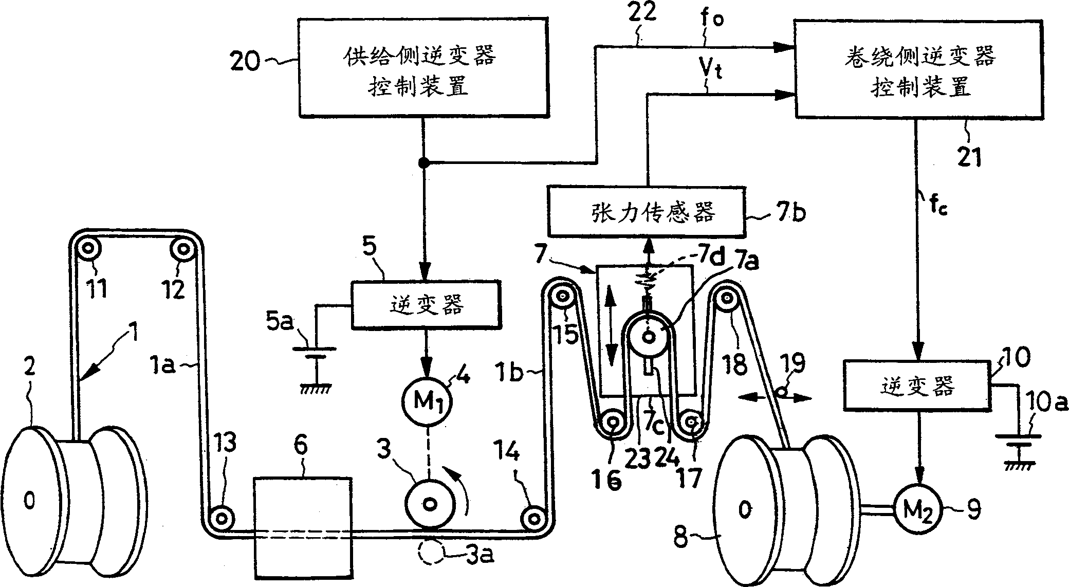
[0029] in accordance with figure 1 The winding device in the wire drawing machine according to the first embodiment of the present invention shown includes: a metal wire 1 as a long object; a supply-side bobbin 2 for supplying the wire 1; a roller 3 as a supply-side rotating body; The motor 4 connected with the roller 3, the inverter 5 as the driving device of the motor 4; the drawing part is the wire drawing part 6; the regulator and the tension detector 7; the reel 8 as the winding side rotating body; Winding-side motor 9 to which winding-side bobbin 8 is connected; inverter 10 as a driving device of motor 9; multiple rollers 11 to 18 arranged on line 1 path; cross arm 19; supply-side inverter 5; and the control device 21 of the winding-side inverter 10.
[0030] The wire 1 is, for example, a large-diameter steel wire 1 a with a diameter of 1 cm on the supply side from the wire-drawing unit 6 , and a small-diameter steel wire 1 b with a diameter of 1 mm on the winding side ...
no. 2 Embodiment
[0058] Next, the winding device of the second embodiment will be described. Form the second embodiment winding device, put figure 1 and figure 2 The control device 21 is transformed into Figure 5 The control device 21a, others with figure 1 same.
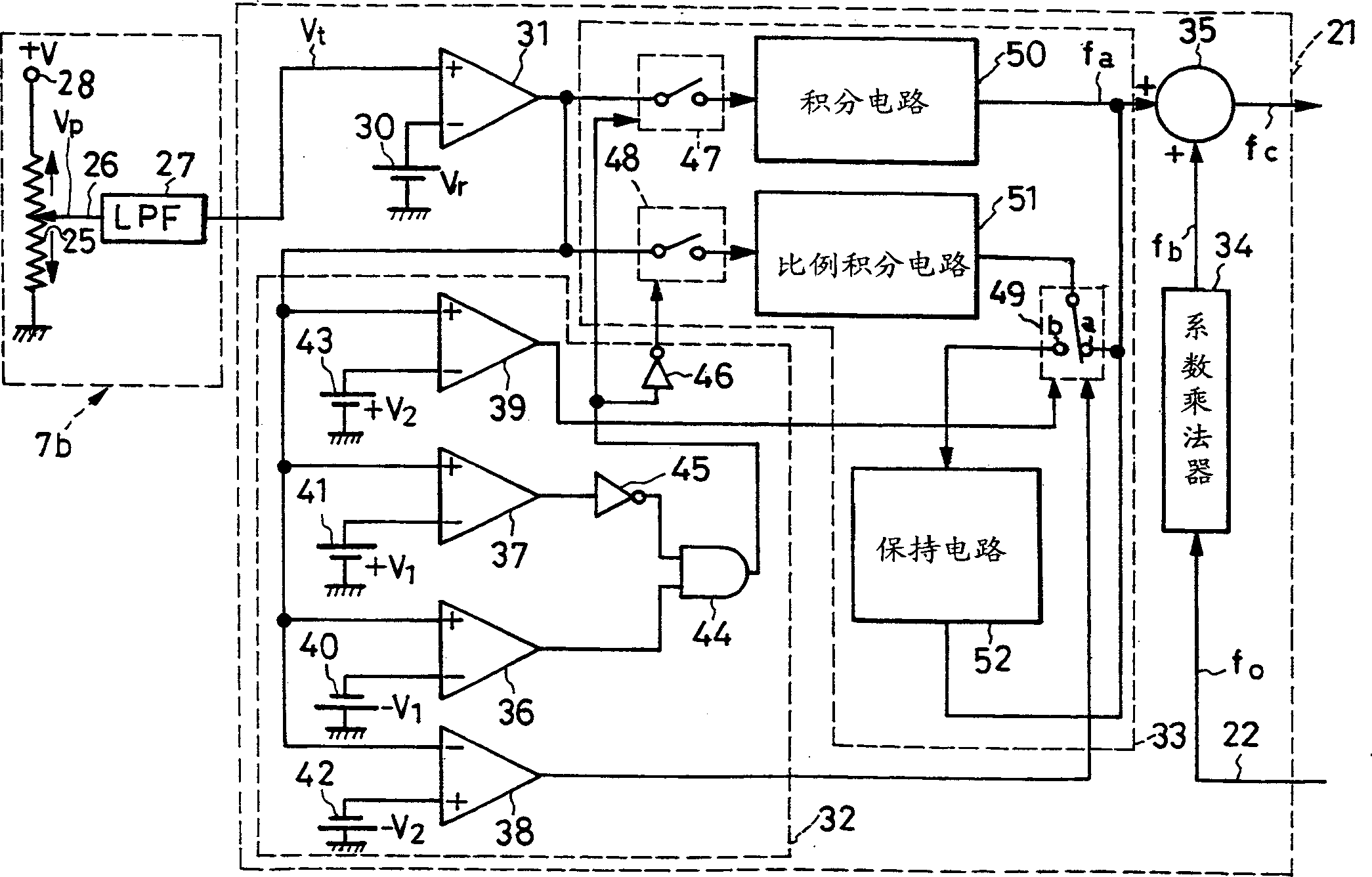
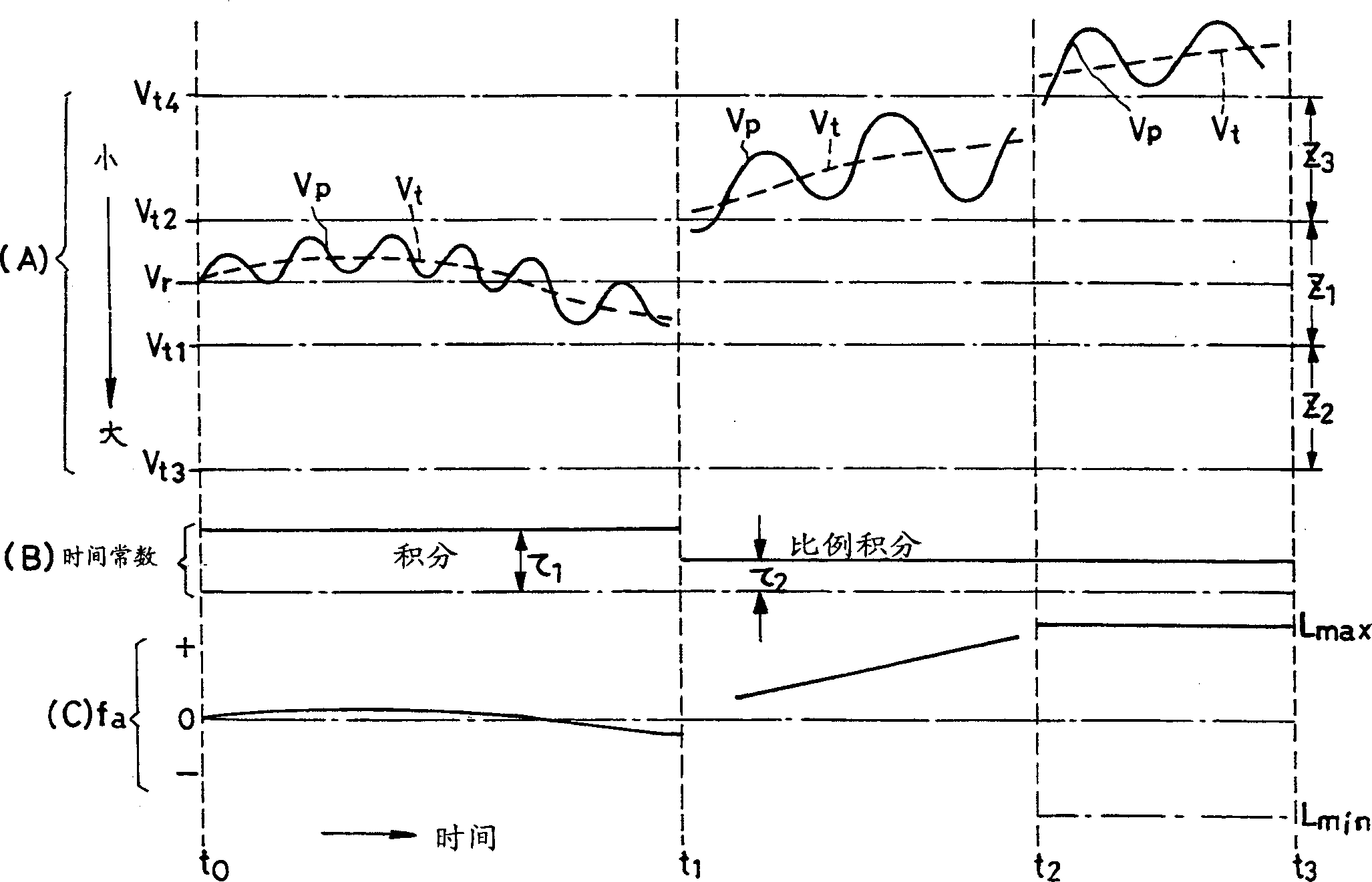
[0059] constitute Figure 5 The control device 21a of the second embodiment, the figure 2 The tension reference voltage source 30, the first, the second, the third and the fourth comparison reference voltage source 40, 41, 42 and 43 of the control device 21 are transformed into a variable tension reference voltage source 30', the first, the second, the The 3rd and 4th comparative reference voltage sources 40', 41', 42' and 43', other and figure 2 same. Such as Figure 6 As shown, the variable tension reference voltage source 30' generates a reference voltage Vr' that gradually decreases from the wire winding start time t1 to the winding end time t2. As a result, the occurrence of figure 1 The tension of the wire 1b inc...
no. 3 Embodiment
[0067] Form the winding device of the 3rd embodiment, put figure 1 and figure 2 The control device 21 is transformed into Figure 7 The control device 21b, others with figure 1 same.
[0068] form Figure 7 The control device 21b, change figure 2 The connecting parts of the first to fourth comparators 36 to 39 and the first to fourth comparison reference voltage sources 40 to 43, and the other figure 2 same. Therefore, in Figure 7 in, for with figure 2 The same parts are marked with the same symbols, and their descriptions are omitted.
[0069] Figure 7 The positive input terminals of the first, second and fourth comparators 36, 37 and 39 and the negative input terminal of the third comparator 38 are connected to the tension sensor 7b. The first, second, third and fourth comparison reference voltage sources 40a, 41a, 42a and 43a connected to the first to fourth comparators 36 to 39 generate image 3 (A) Vt1, Vt2, Vt3 and Vt4.
[0070] As described above, even...
PUM
 Abstract
Description
Claims
Application Information
 - R&D
- Intellectual Property
- Life Sciences
- Materials
- Tech Scout
- Unparalleled Data Quality
- Higher Quality Content
- 60% Fewer Hallucinations
Browse by: Latest US Patents, China's latest patents, Technical Efficacy Thesaurus, Application Domain, Technology Topic, Popular Technical Reports.
© 2025 PatSnap. All rights reserved.Legal|Privacy policy|Modern Slavery Act Transparency Statement|Sitemap|About US| Contact US: help@patsnap.com


