Roller bearing and roller chain mounted with roller bearing

A technology of roller bearing and roller chain, applied in the field of roller chain, can solve the problems of difficult management, high cost, low production efficiency of roller 5, etc.

Inactive Publication Date: 2002-10-16
TSUBAKIMOTO CHAIN CO
View PDF2 Cites 14 Cited by
  • Summary
  • Abstract
  • Description
  • Claims
  • Application Information

AI Technical Summary

Problems solved by technology

Therefore, abrasion occurs so that the smooth rotation of the roller 5 is suppressed
[0007] (2) The contact between the rollers 4 will cause collision noise, and repeated collisions will cause fatigue fracture
[0010] (5) Since the inner side of the collar 5a is difficult to a

Method used


Image

  • Roller bearing and roller chain mounted with roller bearing
  • Roller bearing and roller chain mounted with roller bearing
  • Roller bearing and roller chain mounted with roller bearing

Examples


Embodiment Construction

[0060] The following description is exemplary only and does not limit the invention or its application or use.

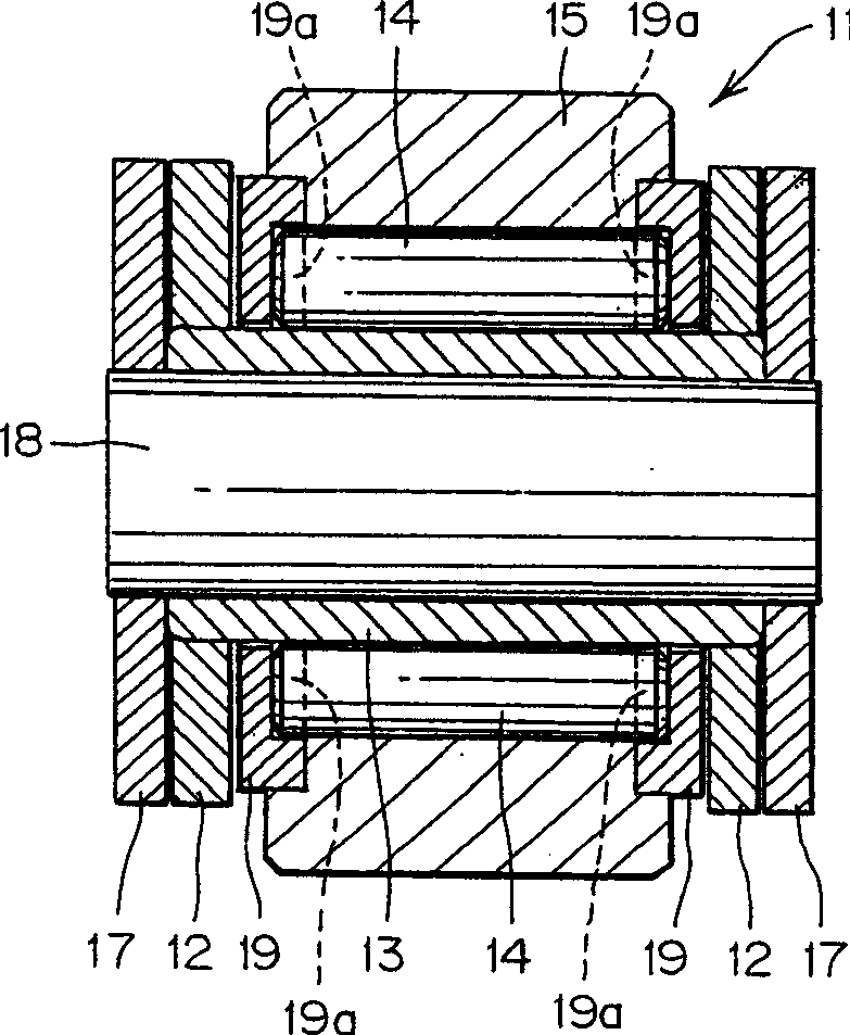
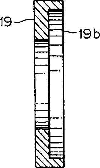
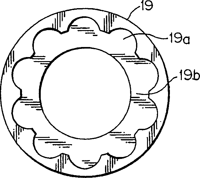
[0061] refer to figure 1 , FIG. 2(A) and FIG. 2(B) describe a first embodiment of the present invention. figure 1 is a sectional view of the roller chain with roller bearings according to the first embodiment of the present invention. Figures 2(A) and 2(B) are used in figure 1 The cage in the roller chain, in particular, Figure 2 (A) is its cross-sectional view, Figure 2 (B) is a top view. exist figure 1 In the roller chain 11 shown in , a plurality of rollers 14 are arranged on the outer circumference of the bushing 13, for example, there are 10 rollers 14 here, and the two ends of the bushing are connected with a pair of inner connecting plates 12, and the rollers Columns 15 are connected to surround the rollers 14 . Moreover, an outer connecting plate 17 is also provided on the outer side of the inner connecting plate 12 , and the outer connecting plates 17 ...


PUM


Abstract

A roller chain equipped with roller bearings, in which a plurality of rollers are arranged between a roller as an outer ring and a bush as an inner ring, including a substantially Ring cage. The cage includes a plurality of pockets for guiding at least a portion of each of the rollers inside the cage.

Description

technical field [0001] The invention relates to a roller bearing and a roller chain equipped with the roller bearing. Background technique [0002] Generally, Japanese Unexamined Patent Application, First Publication No. Sho 62-4112 (Japanese Examined Patent Application, Second Publication No. Japanese Laid-open No. Hei 4-78523) discloses a roller bearing equipped with a roller bearing. child chain. Fig. 22 is a sectional view of the roller chain disclosed in the above-mentioned Japanese Unexamined Patent Application First Publication No. Sho 62-4112. In the roller chain 1 shown in Figure 22, a plurality of rollers 4 for bearings are provided on the outer circumference of the bushing 3, and the two ends of the bushing are connected with a pair of inner connecting plates 2, and the rollers 5 and The rollers 4 are attached to surround the rollers 4, and a thrust bearing receiving plate 6 is inserted into the space between the rollers 5 and the inner connecting plate 2. More...

Claims


Application Information

Patent Timeline
IPC IPC(8): B65G17/38F16C19/50B65G39/20F16C33/46F16C33/52F16G13/06
CPCF16C19/50F16C33/491F16G13/06F16C21/00F16C19/26F16C33/4605
Inventor 佐治智之
Owner TSUBAKIMOTO CHAIN CO
Why Eureka
Try Eureka