Electric flow control valve

A flow control valve, electric technology, applied in the direction of sliding valve, valve detail, multi-way valve, etc., can solve the problems of difficult flow control, adjustment of the degree of inability to open, and lack of freedom in flow control.

Inactive Publication Date: 2002-10-16
PACIFIC INDUSTRIAL CO LTD
View PDF0 Cites 3 Cited by
  • Summary
  • Abstract
  • Description
  • Claims
  • Application Information

AI Technical Summary

Problems solved by technology

Therefore, the entire area of ​​the rotation range of the valve body cannot be used to adjust the opening degree of one of the valve ports, and it is difficult to control the flow rate with high precision.
[0005] In addition, since the opening degree o...

Method used


Image

  • Electric flow control valve
  • Electric flow control valve
  • Electric flow control valve

Examples


Embodiment Construction

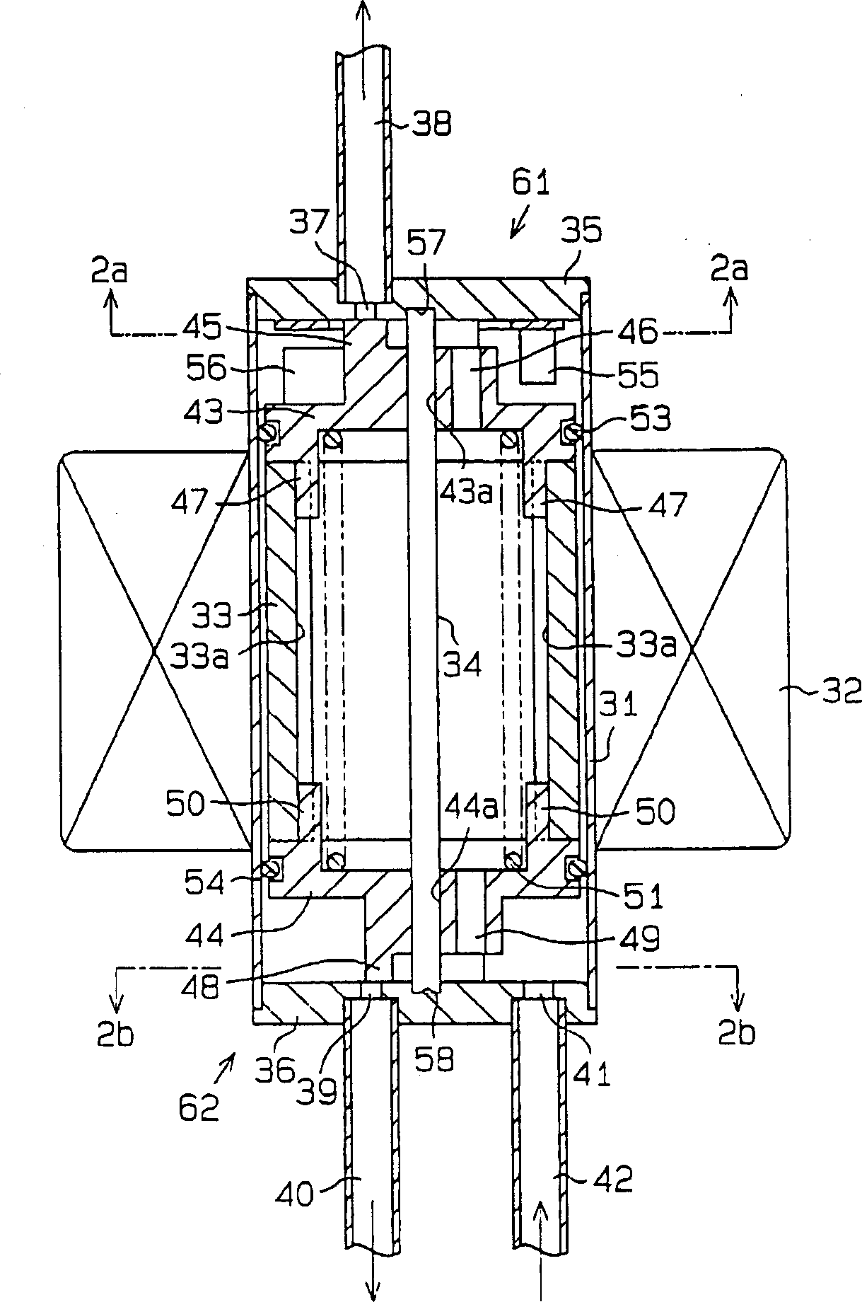
[0019] Refer below Figure 1~3 , an embodiment of the present invention is described. figure 1 The shown electric flow control valve is fitted, for example, in a coolant circuit of the heat pump type (not shown in the figure). The control valve comprises a cylindrical housing 31, the two ends of the cylindrical housing 31 are open, a first valve seat 35 and a second valve seat 36, and the first valve seat 35 and the second valve seat 36 are fixed to the valve seat in an airtight manner. The two ends of the cylindrical shell 31. The cylindrical case 31 is formed of non-magnetic metal. Around this cylindrical case 31, an electromagnetic coil 32 is installed. Electric current is supplied to the solenoid coil 32 through a controller (not shown in the figure).

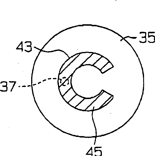
[0020] Each valve seat 35, 36 is disc-shaped. The first valve seat 35 has a first valve port 37 at a position away from the center, and the first valve port 37 communicates with the inner space of the cylindrical casin...


PUM


Abstract

A first throttling valve mechanism and a second throttle valve mechanism are arranged at both axial ends of the casing. Each throttling valve mechanism includes a valve seat and a valve body, the valve seat is fixed on the shell, and the valve body faces the valve seat. The second valve seat has an inflow port for feeding coolant into the housing interior. Each valve seat has a valve port, and the valve port is used to let the coolant sent into the inside of the casing flow out to the outside of the casing. Each valve body rotates so as to adjust the degree of opening of the valve port while in contact with the corresponding valve seat. The rotor provided inside the housing is connected to the two valve bodies so as to rotate the two valve bodies. Rotation control is performed on the two valve bodies so as to adjust the outflow of coolant through the respective valve ports through the corresponding valve bodies.

Description

technical field [0001] The present invention relates to an electric flow control valve that switches a coolant flow path in a coolant circuit and regulates the coolant flow rate. Background technique [0002] For example, a heat pump type coolant circuit is equipped with an electric flow control valve for switching the flow paths of the coolant in the coolant circuit and adjusting the flow rate of the coolant in each path. As such a control valve, a type including, for example, a planar valve seat having a plurality of (for example, two) valve ports, and a valve body in sliding contact with the valve seat has been proposed. The valve body rotates around an axis perpendicular to the surface of the valve seat while in contact with the valve seat. The opening degree of each valve port is adjusted by the rotation of the valve body. In addition, the rotation range of the valve body is limited within an angle range of less than 360 degrees by the stopper. [0003] A coolant inf...

Claims


Application Information

Patent Timeline
IPC IPC(8): F16K3/02F16K11/074F16K31/02F16K31/04F25B41/04
Inventor 丰田和政
Owner PACIFIC INDUSTRIAL CO LTD
Why Eureka
Try Eureka