Linkage System

a technology of linking system and parallel link, which is applied in the direction of gearing, mechanical control devices, instruments, etc., can solve the problems of increasing the size of the parallel link mechanism, bulkiness of the entire operating device, and the weight of the tool carried on the traveling plate,

Inactive Publication Date: 2008-02-07
NTN CORP
View PDF0 Cites 32 Cited by
  • Summary
  • Abstract
  • Description
  • Claims
  • Application Information

AI Technical Summary

Benefits of technology

[0014]A passage for supplying a control medium from the input member to the output member may be arranged in an inner space enclosed by the link mechanisms, which is preferable in that wiring and tubing will be easy.

Problems solved by technology

On the other hand, if the operating range of the traveling plate needs to be increased, the links have to be extended because each link has a relatively small operating angle range, which increases the size of the parallel link mechanism and causes bulkiness of the entire operating device.
Further, because of low rigidity of the mechanism, the weight of the tool carried on the traveling plate, i.e., the load capacity of the traveling plate, has to be limited to a small range.

Method used


Image

  • Linkage System
  • Linkage System
  • Linkage System

Examples


Embodiment Construction

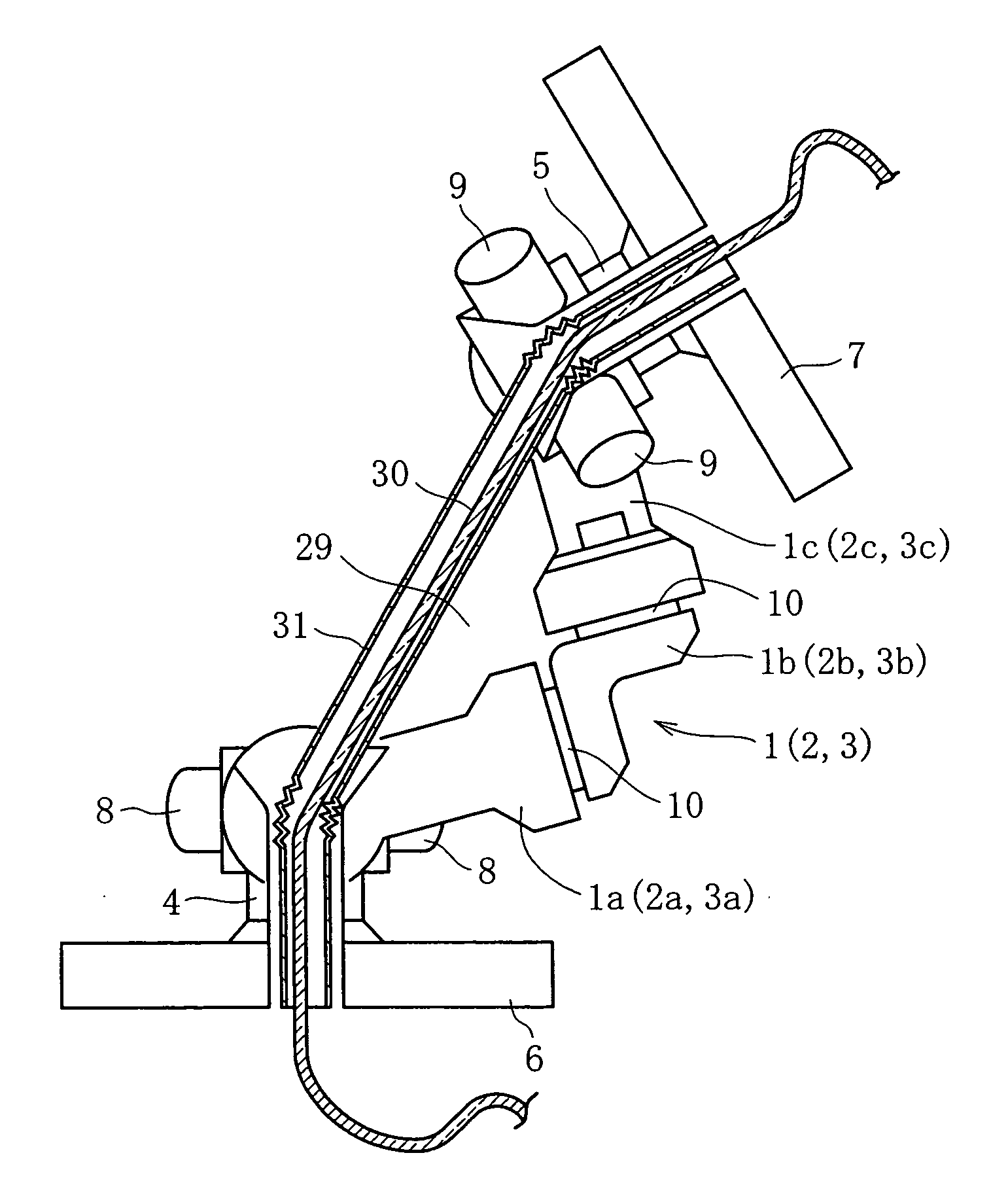
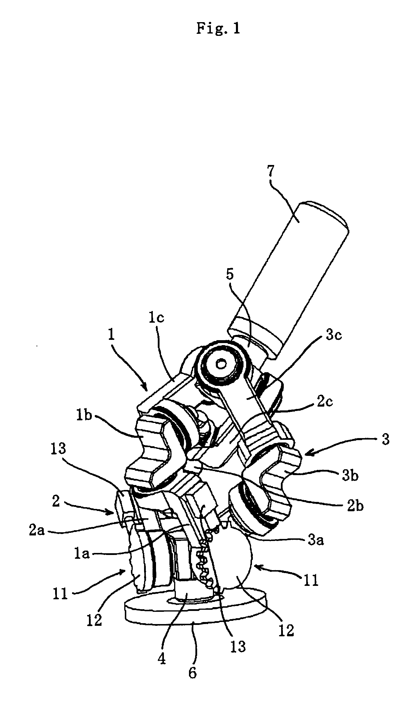
[0025]The embodiment shown in FIG. 1 includes three sets of link mechanisms 1 to 3 for use, for example, as a parallel link mechanism or a robot joint that performs complex processing or handling of goods in a three-dimensional space at high speed and with high precision.

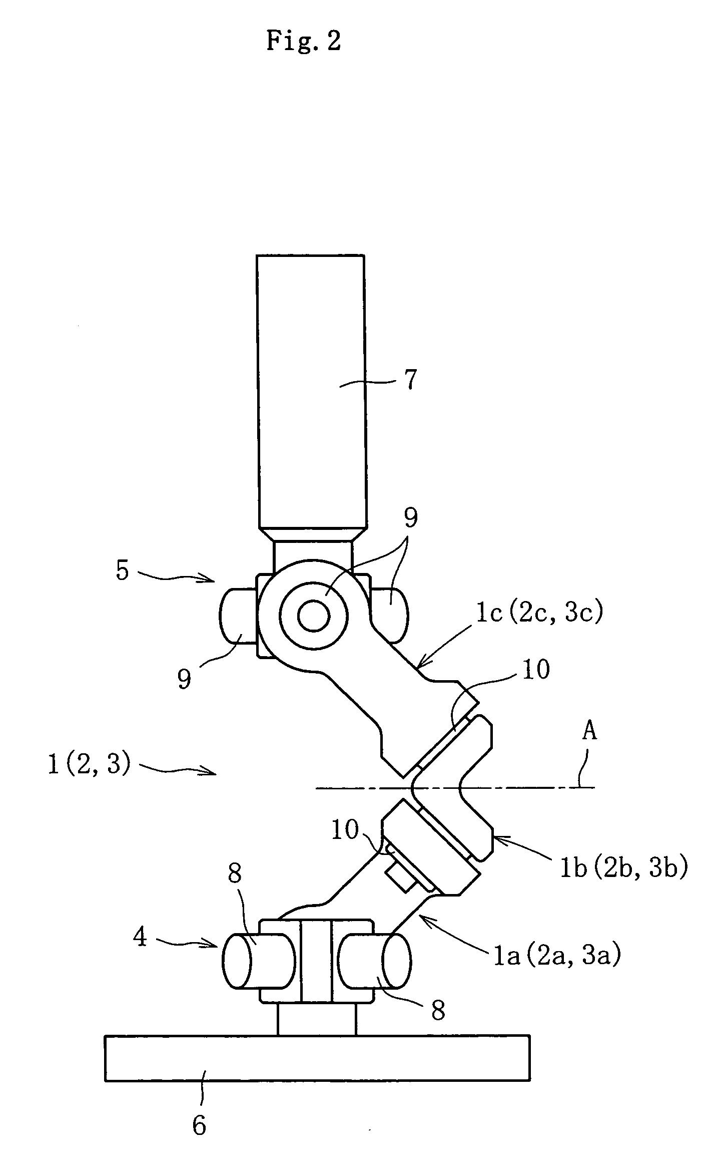
[0026]An input member 6 and an output member 7 are coupled together by the three link mechanisms 1 to 3 (first to third link mechanisms), each link mechanism having a geometrically identical shape. The input member 6 is mounted to an input-side component of equipment in which this operating device is incorporated, which is, for example, a stationary part, and the output member 7 is attached to the output-side component of the equipment, which is, for example, a movable part. In this embodiment, as illustrated, the input member 6 has a disc-like shape, while the output member 7 has a shaft-like shape.

[0027]Each link mechanism 1 to 3 forms a three-link chain, including an input end link member 1a (2a, 3a), a center li...


PUM


Abstract

A linkage system is provided which is equipped with a compact and high-rigidity link mechanism with a large load capacity. The linkage system includes three or more link mechanisms. Each link mechanism consists of a center link member and end link members rotatably coupled to the center link member and to link hubs that are provided to an input member and an output member, respectively. An input side and an output side of a center cross-sectional plane of each link mechanism are geometrically identical. One or more of revolute joints of two or more of the link mechanisms that are coupled to the input member are provided with a stopping mechanism for stopping the output member at a given position.

Description

BACKGROUND OF THE INVENTION[0001]1. Field of the Invention[0002]The present invention relates to a linkage system for use as a link mechanism such as a parallel link mechanism or a robot joint that performs complex processing or handling of goods in a three-dimensional space at high speed and with high precision.[0003]2. Description of the Related Art[0004]An operating device equipped with a parallel link mechanism that performs complex processing or handling of goods in a three-dimensional space at high speed and with high precision is known (see, for example, Japanese Patent Laid-Open Publication No. 2000-94245).[0005]This operating device includes a parallel link mechanism, which has a plurality of links that connect a base plate and a traveling plate and cooperatively extend and retract to change the position and orientation of the traveling plate relative to the base plate. Tool is attached to the traveling plate of this parallel link mechanism, while a workpiece is held on a t...

Claims


Application Information

Patent Timeline
Patent Type & Authority Applications(United States)
IPC IPC(8): G05G3/00B25J17/02G05G5/06
CPCB25J17/0266G05G5/065Y10T74/20329Y10T74/20012B25J9/0048G05G7/02G05G25/02
Inventor SONE, KEISUKENAKAKOJI, MASAFUMIIWAMOTO, KENICHI
Owner NTN CORP
Why Eureka
Try Eureka