Movable body drive method and movable body drive system, pattern formation method and apparatus, exposure method and apparatus, and device manufacturing method

a technology of movable bodies and drive systems, applied in the direction of dynamo-electric components, printers, instruments, etc., can solve the problems of inferior lack of measurement value linearity of encoders, and inability to accurately measure the long-term stability of laser interferometers, etc., to achieve good precision and good precision

Inactive Publication Date: 2009-02-12
NIKON CORP
View PDF30 Cites 30 Cited by
  • Summary
  • Abstract
  • Description
  • Claims
  • Application Information

AI Technical Summary

Benefits of technology

[0039]According to this apparatus, for relative movement of the energy beam irradiated on the object from the patterning device and the object, the movable body on which the object is mounted is driven wi...

Problems solved by technology

However, requirements for a stage position control with higher precision are increasing due to finer patterns that accompany higher integration of semiconductor devices, and now, short-term variation of measurement values due to temperature fluctuation of the atmosphere on the beam path of the laser interferometer or the influence of temperature gradient has come to occupy a large percentage in the overlay budget.
Meanwhile, as a measurement device besides the laser interferometer used for position measurement of the stage, an encoder can be used, however, because the encoder uses a scale, which lacks in mechanical long-term stability (drift of grating pitch, fixed p...

Method used


Image

  • Movable body drive method and movable body drive system, pattern formation method and apparatus, exposure method and apparatus, and device manufacturing method
  • Movable body drive method and movable body drive system, pattern formation method and apparatus, exposure method and apparatus, and device manufacturing method
  • Movable body drive method and movable body drive system, pattern formation method and apparatus, exposure method and apparatus, and device manufacturing method

Examples


Embodiment Construction

[0061]Hereinafter, an embodiment of the present invention will be described, referring to FIGS. 1 to 20.

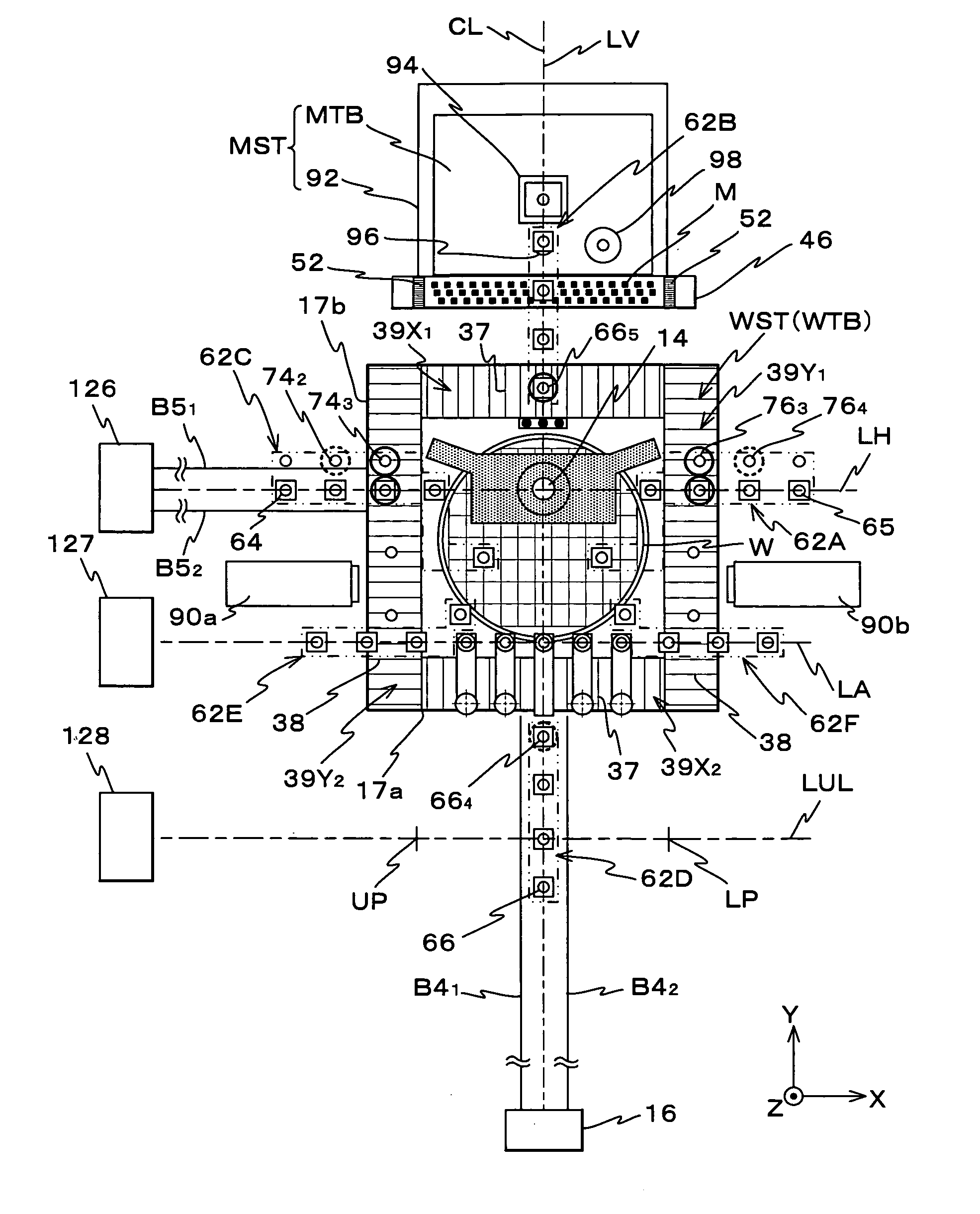
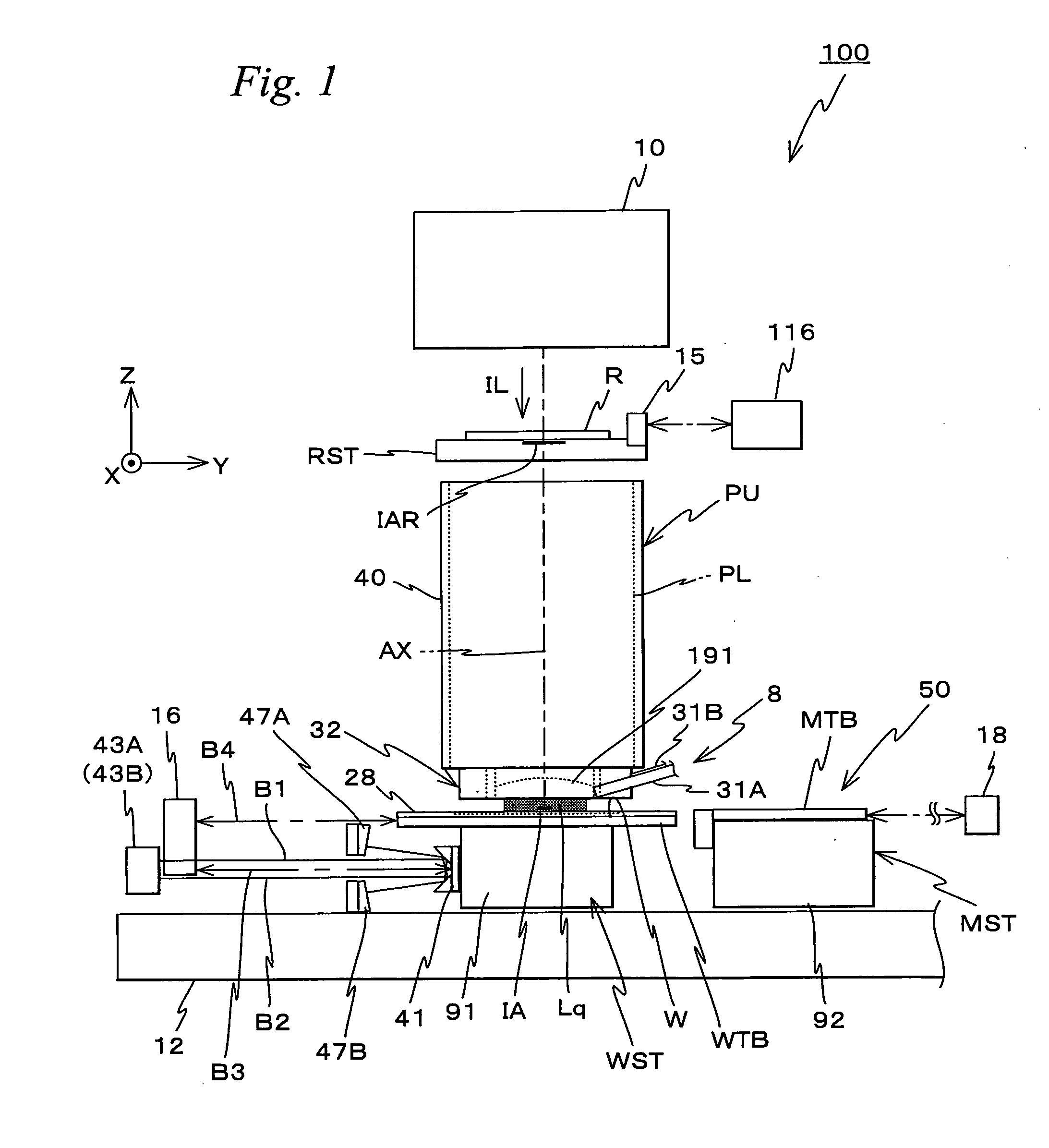
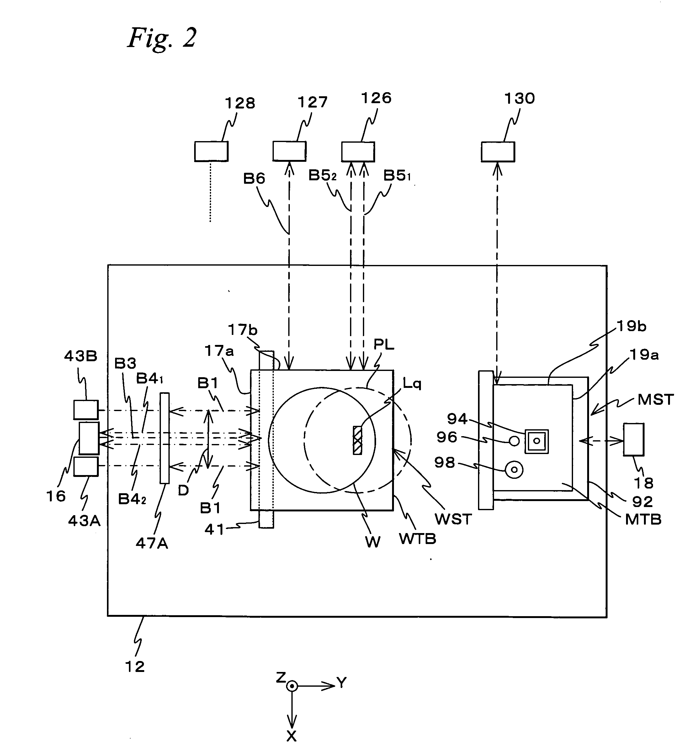
[0062]FIG. 1 shows a schematic configuration of an exposure apparatus 100 in the embodiment. Exposure apparatus 100 is a projection exposure apparatus of the step-and-scan method, namely the so-called scanner. As it will be described later, a projection optical system PL is arranged in the embodiment, and in the description below, a direction parallel to an optical axis AX of projection optical system PL will be described as the Z-axis direction, a direction within a plane orthogonal to the Z-axis direction in which a reticle and a wafer are relatively scanned will be described as the Y-axis direction, a direction orthogonal to the Z-axis and the Y-axis will be described as the X-axis direction, and rotational (inclination) directions around the X-axis, the Y-axis, and the Z-axis will be described as θx, θy, and θz directions, respectively.

[0063]Exposure apparatus 100 is equipped ...


PUM


Abstract

Positional information of a stage within a movement plane is measured, using three encoders which include at least one each of an X encoder and a Y encoder. Based on position measurement values of the stage, the encoder used in position measurement is switched from an encoder (Enc1, Enc2 and Enc3) to an encoder (Enc4, Enc2 and Enc3). On the switching, a coordinate linkage method or a phase linkage method is applied to set an initial value of an encoder (Enc4) which is to be newly used. Accordingly, position measurement values of the stage before and after the switching are stored even though the encoder used in position measurement of the stage is sequentially switched, and the stage can be driven accurately two-dimensionally.

Description

CROSS-REFERENCE TO RELATED APPLICATIONS[0001]This non-provisional application claims the benefit of Provisional Application No. 60 / 935,385 filed Aug. 9, 2007, and Provisional Application No. 61 / 006,795 filed Jan. 31, 2008, the disclosures of which are hereby incorporated herein by reference in its entirety.BACKGROUND OF THE INVENTION[0002]1. Field of the Invention[0003]The present invention relates to movable body drive methods and movable body drive systems, pattern formation methods and apparatuses, exposure methods and apparatuses, and device manufacturing methods, and more particularly, to a movable body drive method and a movable body drive system that drives a movable body along a predetermined plane, a pattern formation method using the movable body drive method and a pattern formation apparatus equipped with the movable body drive system, an exposure method using the movable body drive method, and an exposure apparatus equipped with the movable body drive system, and a devic...

Claims


Application Information

Patent Timeline
IPC IPC(8): G03B27/42G03B27/58H02K41/00
CPCG03F7/70508G03F7/70725G03F9/7088G03F7/7085G03F7/70775
Inventor SHIBAZAKI, YUICHI
Owner NIKON CORP
Why Eureka
Try Eureka