

Domestic refuse incinerator
A technology of domestic waste incineration and grate, applied in incinerators, grate, combustion type and other directions, can solve the problems of insufficient combustion of waste material layer, difficulty in achieving ash slag thermal reduction rate, and difficulty in uniform thickness, etc. The effect of reducing secondary pollution, constant size and normal ventilation
- Summary
- Abstract
- Description
- Claims
- Application Information
AI Technical Summary
Benefits of technology
Problems solved by technology
Method used
Image

Examples
Embodiment 1
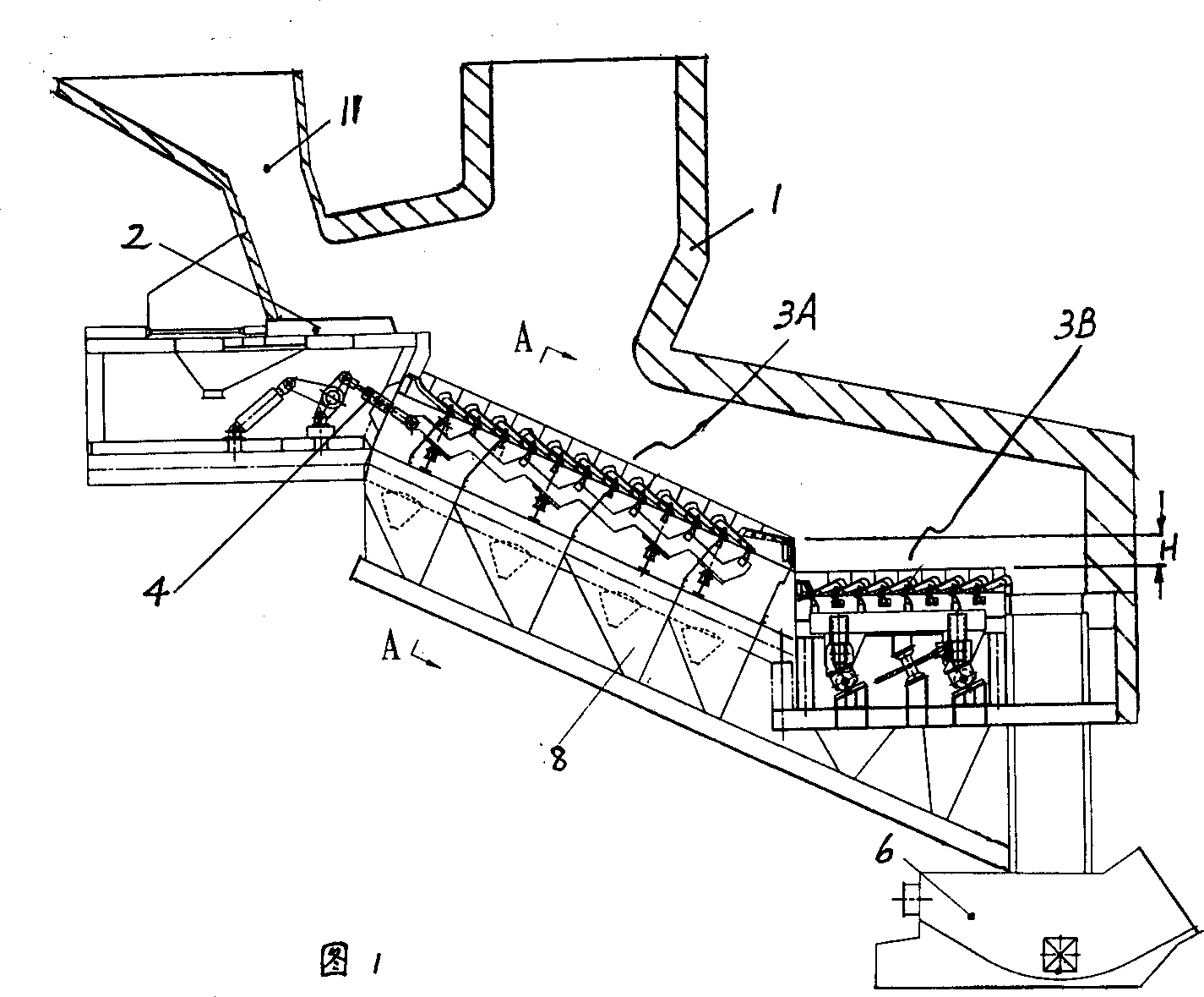
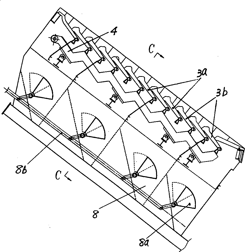
[0020] Embodiment 1. The structure of the domestic waste incinerator of this embodiment can be seen from Fig. 1- image 3 As can be seen in the figure, it includes a furnace body 1 with a hopper 11, a feeder 2 installed in the furnace body, a fire grate 3, an air chamber 5 located under the fire grate, and a slag extractor 6, wherein the fire grate piece of the fire grate 3 It includes a fixed piece 3a fixed on the furnace body and a movable piece 3b connected to the reciprocating rod 4, and the fixed piece and the movable piece are arranged at intervals in the grate moving direction, that is, a row of fixed pieces is arranged in front 1, between the two rows of movable pieces in the back, the same row of movable pieces is arranged between the front and back two rows of fixed pieces; the whole grate is divided into a front section 3A close to the hopper and a back section 3B away from the hopper along the running direction of the garbage. The downward-sloping reverse-push grat...
Embodiment 2
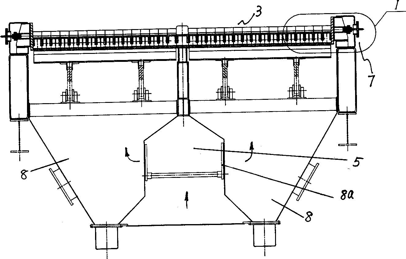
[0022] Embodiment 2. The structure of the domestic waste incinerator of the present embodiment can be seen from Fig. 1, figure 2 and Figure 4 It can be seen from the figure that the difference from Example 1 is that its fire grate 3 has a side seal compensation device 7, which includes a fire grate support 7a, a sealed box 7b integrated with the fire grate support, and a fire grate 3. The side sealing block 7c and the spring 7d are fixedly connected together and can move in the sealed box when the grate expands with heat and contracts with cold.
[0023] When the fire grate expands with heat or contracts with cold, the side sealing block 7c is pushed outwards in the sealed box by the expansion force ( Figure 4 The middle is the right outer side) to move, and when the grate shrinks, the spring 7d pushes the side sealing block 7c to the inner side ( Figure 4 middle is the left side) to move; regardless of thermal expansion or cold contraction, the side seal compensation dev...
Embodiment 3
[0025] Embodiment 3. The structure of the domestic waste incinerator of this embodiment can be seen from Fig. 1- image 3 It can be seen in that, the difference from Embodiment 1 or 2 is that a group of compartments 8 independent of each other are set under the grate, each compartment has a ventilating port communicated with the air chamber 5, and the venting port has a There is a damper 8a that can adjust the air intake.
[0026] When the incinerator is working, the primary air intake enters the compartment 8 through the air chamber 5 through the damper 8a ( figure 2 Indicate its flow direction with the solid line arrow), then enter the garbage material layer through the ventilation holes 3c provided on the grate sheet; image 3 It can be seen in the figure that all dampers can be adjusted through a linkage rod 8b to change the air intake.
[0027] Each damper can also be connected with a microcomputer control system, at this moment, the effective adjustment of the air volu...
PUM
 Abstract
Description
Claims
Application Information