Air distribution system for small household garbage pyrolysis and gasification incinerator and incinerator thereof

A domestic waste, pyrolysis and gasification technology, applied in the direction of incinerators, combustion types, combustion equipment, etc., can solve problems such as the inability to achieve an ideal and stable flow field in the furnace

Pending Publication Date: 2022-05-17
尊峰环保科技有限公司
View PDF0 Cites 0 Cited by
  • Summary
  • Abstract
  • Description
  • Claims
  • Application Information

AI Technical Summary

Problems solved by technology

[0008] The technical problem to be solved by the present invention is to provide an air distribution system and an incinerator for a small domestic waste pyrolysis gasification incinerator, so as to solve the problem that the waste pyrolysis gasification incinerator in the prior art cannot realize an ideal and stable furnace. internal flow problem

Method used


Image

  • Air distribution system for small household garbage pyrolysis and gasification incinerator and incinerator thereof
  • Air distribution system for small household garbage pyrolysis and gasification incinerator and incinerator thereof
  • Air distribution system for small household garbage pyrolysis and gasification incinerator and incinerator thereof

Examples


Embodiment 1

[0066] Such as Figure 1-6 As shown, the air distribution system for the small domestic waste pyrolysis gasification incinerator proposed by the embodiment of the present invention includes:

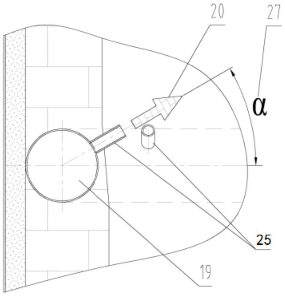
[0067] Annular air duct 19, said annular air duct 19 is arranged on the inside of the side wall of the body of heater 1, and is circumferentially provided with an inward blowing port 25 communicating with the furnace 2; the gas outlet of said inward blowing port 25 points to said Centerline of furnace 2;

[0068] Air supply main pipe 11, described air supply main pipe 11 is arranged on the outside of described furnace body 1, and is provided with first road air duct 6, second road air duct 8, third road air duct 10;

[0069] The first air duct 6 passes through the side wall of the furnace body 1 and communicates with the annular air duct 19;

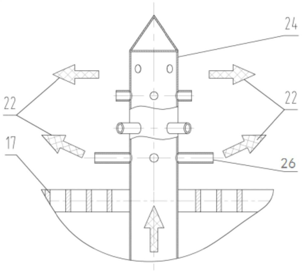
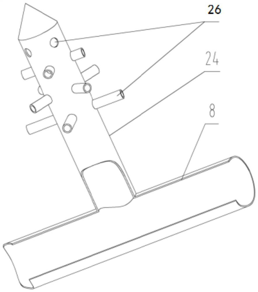
[0070] The second air duct 8 passes through the side wall of the furnace body 1 and extends to the ash chamber 15; the second air duct 8 is prov...

Embodiment 2

[0088] Such as Figure 7-13 As shown, this embodiment proposes an incinerator, including the air distribution system for a small domestic waste pyrolysis gasification incinerator described in Embodiment 1. The incinerator at least includes: a furnace body 1 , a fire grate 17 , and a slag collecting bucket 13 .

[0089]As a preferred implementation of this embodiment, the incinerator includes: a furnace body 1, a fire grate 17, a smoke collecting pipe 34, an exhaust pipe 3, a secondary combustion chamber 35, and a slag collecting hopper 13;

[0090] The interior of the furnace body 1 is a cavity, and the top is provided with a feed port 36 and a feed door 37 capable of sealingly fitting with the feed port 36 .

[0091] The fire grate 17 is located in the furnace body 1, and divides the cavity of the furnace body 1 into the upper furnace 2 and the lower ash chamber 15; that is, the fire grate 17 and the furnace body 1 The space enclosed by the inner surface of the side wall, t...


PUM


Abstract

The invention provides an air distribution system for a small household garbage pyrolysis and gasification incinerator. The air distribution system comprises an annular air pipe and an air supply header pipe, and the air supply header pipe is provided with a first air pipe, a second air pipe and a third air pipe. According to the air distribution system for the small household garbage pyrolysis and gasification incinerator, blending combustion air is divided into three paths of air to be actively conveyed to different reaction areas of the hearth so as to maintain garbage reaction, the flow field in the incinerator is actively controlled, and the oxygen supply amount of the corresponding areas can be actively controlled according to the aerobic rule of garbage in the different reaction areas; the stability of a hearth flow field is improved, the reaction process of garbage is optimized, the external energy consumption of various reactions of the garbage and the ignition loss of ash are reduced, the component stability of pyrolysis gas and the operation stability of a secondary combustion chamber are improved, and further treatment of the pyrolysis gas is facilitated; and favorable conditions are created for the incinerator to achieve a better emission level.

Description

technical field [0001] The invention relates to the technical field of domestic waste treatment, in particular to an air distribution system for a small domestic waste pyrolysis gasification incinerator and an incinerator thereof. Background technique [0002] Decentralized domestic waste incineration treatment is another new trend to solve urban and rural domestic waste in addition to large-scale centralized incineration for power generation, and it is a necessary supplement for large-scale centralized incineration for power generation. The key to the development of decentralized domestic waste incineration treatment is the mature technology of small domestic waste incinerators that strictly meet the pollutant discharge standards. The study found that the small domestic waste incinerator based on the pyrolysis incineration process can achieve extremely low emission levels due to important pollution factors such as dioxins and carbon monoxide, and has good development prospe...

Claims


Application Information

Patent Timeline
IPC IPC(8): F23G5/44F23L1/00F23G5/50F23G5/027F23G5/04F23G5/16
CPCF23G5/44F23L1/00F23G5/50F23G5/027F23G5/04F23G5/16F23G2201/30F23G2201/10F23G2202/103Y02E20/34
Inventor 王曙辉冯艳田甜张建超贺志峰喻革陈忠骏廖雨佳言政
Owner 尊峰环保科技有限公司
Why Eureka
Try Eureka