
Domestic refuse incinerator

A technology for domestic waste incineration and grate, which is applied in incinerators, grate, combustion type and other directions, can solve the problems of insufficient combustion of the waste material layer, difficulty in achieving the ash slag thermal reduction rate, and difficulty in uniform thickness, etc. The effect of reducing secondary pollution, constant size and normal ventilation

Inactive Publication Date: 2004-08-18
屠柏锐 +2
View PDF0 Cites 8 Cited by
  • Summary
  • Abstract
  • Description
  • Claims
  • Application Information

AI Technical Summary

Problems solved by technology

[0002] The existing domestic waste incinerator includes a furnace body with a hopper, a feeder installed in the furnace body, a fire grate, an air chamber under the fire grate, and a slag extractor; wherein the fire grate pieces in the fire grate include The fixed piece fixed on the furnace body and the movable piece arranged between the two adjacent fixed pieces at intervals and connected with the reciprocating moving parts; according to the movement characteristics of the garbage on the grate, the grate can be divided into forward push type and There are two types of inclined reverse push type. The moving direction of the forward push grate is consistent with the direction of the garbage moving in the furnace, while the movable piece of the inclined reverse push grate is opposite to the downward direction of the garbage; now Disadvantages of domestic waste incinerators are: 1) If all the furnace body adopts forward-push grate, the running waste is almost in a relatively static state and cannot be stirred by itself, so the waste material layer cannot be fully burned and the combustion efficiency is low , It is difficult to achieve the index of thermal ignition reduction rate of ash and slag; if the furnace body adopts reverse-push grate, the garbage material layer is simultaneously subjected to the dual action of the upward thrust of the movable piece and the gravity component of the garbage, and is stirred in a spiral manner. However, since the thickness of the material layer needs to be established by other equipment (such as slag drum, etc.), its thickness is not easy to be uniform. Blow out the "burner", but the place where the material layer is thick is not easy to burn through, and the fireball cannot be loosened, so the garbage is discharged out of the furnace before it is completely burned; For the furnace, its primary air enters the top of the grate through the ventilation slots reserved on the side of the grate, and the ventilation slots can ensure sufficient ventilation in the initial stage of the grate operation, but as time goes by, due to the wear and tear of the grate The clogging of ash and slag makes the ventilation cross section gradually smaller, resulting in worsening combustion effect; 3) The air chamber cannot meet the different requirements for air volume in different garbage incineration areas on the grate, so the combustion of garbage cannot be in the best state; 4) The thermal expansion and contraction of the grate during work will cause changes in the ventilation section, making the air intake unstable and the combustion effect difficult to control

Method used


Image

  • Domestic refuse incinerator
  • Domestic refuse incinerator
  • Domestic refuse incinerator

Examples


Embodiment 1

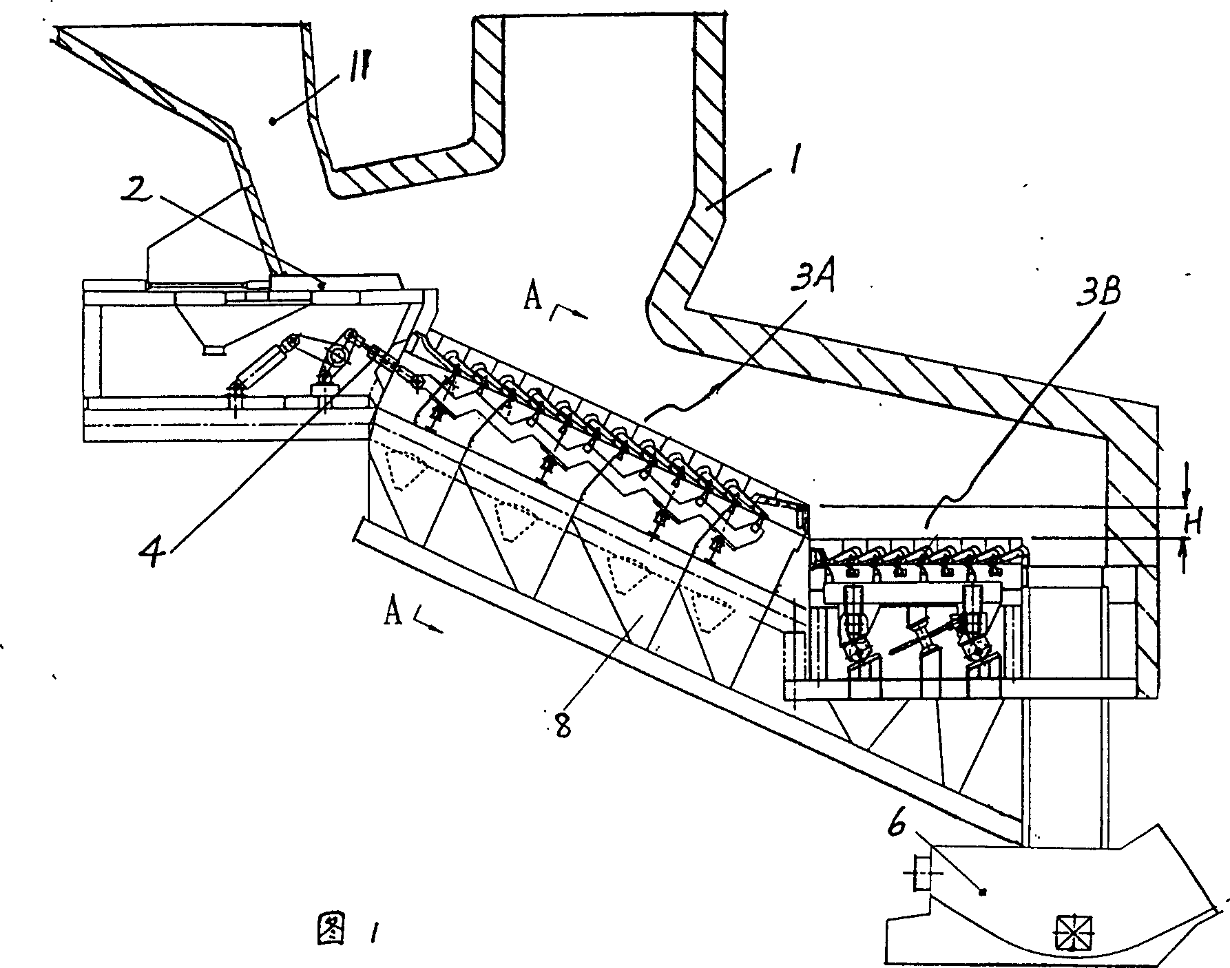
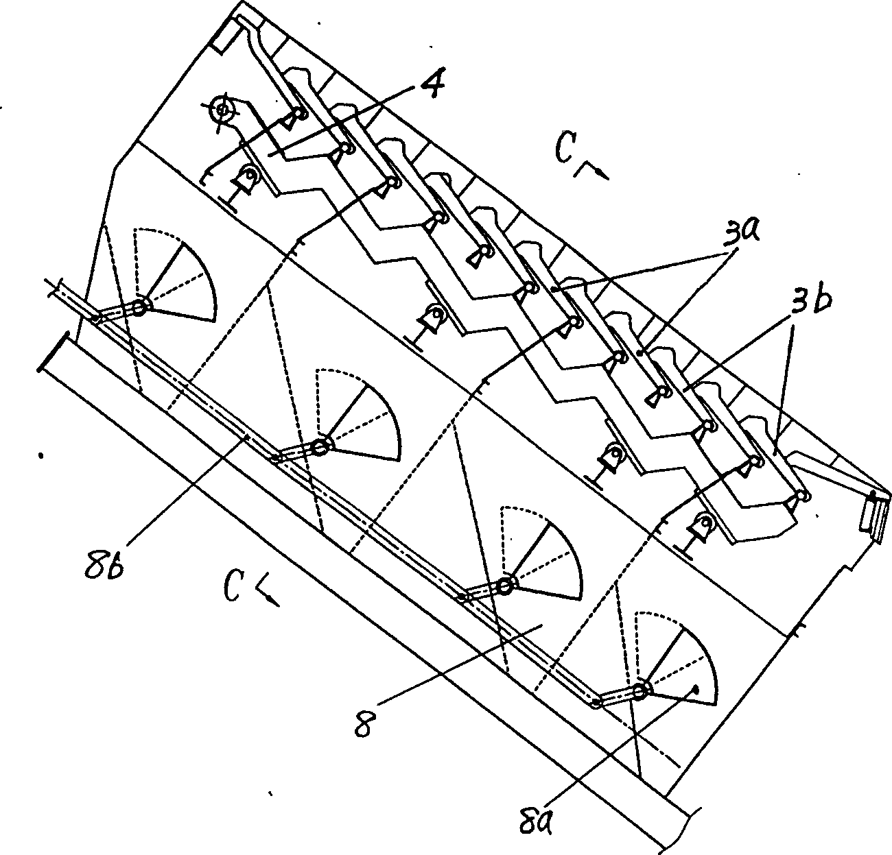
[0020] Embodiment 1. The structure of the domestic waste incinerator of this embodiment can be seen from Fig. 1- image 3 As can be seen in the figure, it includes a furnace body 1 with a hopper 11, a feeder 2 installed in the furnace body, a fire grate 3, an air chamber 5 located under the fire grate, and a slag extractor 6, wherein the fire grate piece of the fire grate 3 It includes a fixed piece 3a fixed on the furnace body and a movable piece 3b connected to the reciprocating rod 4, and the fixed piece and the movable piece are arranged at intervals in the grate moving direction, that is, a row of fixed pieces is arranged in front 1, between the two rows of movable pieces in the back, the same row of movable pieces is arranged between the front and back two rows of fixed pieces; the whole grate is divided into a front section 3A close to the hopper and a back section 3B away from the hopper along the running direction of the garbage. The downward-sloping reverse-push grat...

Embodiment 2

[0022] Embodiment 2. The structure of the domestic waste incinerator of the present embodiment can be seen from Fig. 1, figure 2 and Figure 4 It can be seen from the figure that the difference from Example 1 is that its fire grate 3 has a side seal compensation device 7, which includes a fire grate support 7a, a sealed box 7b integrated with the fire grate support, and a fire grate 3. The side sealing block 7c and the spring 7d are fixedly connected together and can move in the sealed box when the grate expands with heat and contracts with cold.

[0023] When the fire grate expands with heat or contracts with cold, the side sealing block 7c is pushed outwards in the sealed box by the expansion force ( Figure 4 The middle is the right outer side) to move, and when the grate shrinks, the spring 7d pushes the side sealing block 7c to the inner side ( Figure 4 middle is the left side) to move; regardless of thermal expansion or cold contraction, the side seal compensation dev...

Embodiment 3

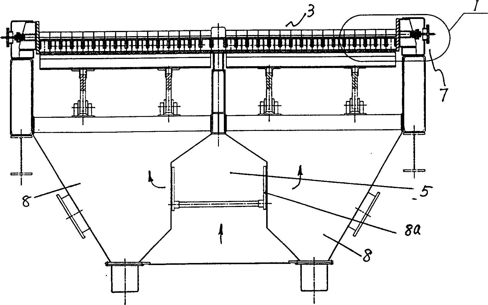
[0025] Embodiment 3. The structure of the domestic waste incinerator of this embodiment can be seen from Fig. 1- image 3 It can be seen in that, the difference from Embodiment 1 or 2 is that a group of compartments 8 independent of each other are set under the grate, each compartment has a ventilating port communicated with the air chamber 5, and the venting port has a There is a damper 8a that can adjust the air intake.

[0026] When the incinerator is working, the primary air intake enters the compartment 8 through the air chamber 5 through the damper 8a ( figure 2 Indicate its flow direction with the solid line arrow), then enter the garbage material layer through the ventilation holes 3c provided on the grate sheet; image 3 It can be seen in the figure that all dampers can be adjusted through a linkage rod 8b to change the air intake.

[0027] Each damper can also be connected with a microcomputer control system, at this moment, the effective adjustment of the air volu...


PUM


Abstract

The domestic refuse incinerator is characterized by that two-stage reciprocating grate, it is suitable for incinerating low-calority high water content and non-sorted domestic refuse, it comprises furnace body with bunker, feeding machine, fire grate, air chamber positioned under the grate and ash-discharge hole, in which said fire grate comprises fixed grate segments fixed on the furnace body and movable grate segments connected on the reciprocating bar. Said fire grate can be divided into two portions of front-stage grate and rear-stage grate, between them there is a position head with a certain height, said fire grate can make refuse automatically be turned, stirred and crushed, and its air intake can be regulated conveniently, and the refuse can be fully incinerated.

Description

technical field [0001] The invention relates to an incineration device for domestic garbage, in particular to a two-stage reciprocating fire grate and an air chamber at the lower part of the incinerator. It can be used especially for incineration of low calorific value, high moisture, unsorted domestic waste. Background technique [0002] The existing domestic waste incinerator includes a furnace body with a hopper, a feeder installed in the furnace body, a fire grate, an air chamber under the fire grate, and a slag extractor; wherein the fire grate pieces in the fire grate include The fixed piece fixed on the furnace body and the movable piece arranged between the two adjacent fixed pieces at intervals and connected with the reciprocating moving parts; according to the movement characteristics of the garbage on the grate, the grate can be divided into forward push type and There are two types of inclined reverse push type. The moving direction of the forward push grate is ...

Claims


Application Information

Patent Timeline
Patent Type & Authority Patents(China)
IPC IPC(8): F23G5/02F23G5/033F23G5/04F23H11/12
Inventor 屠柏锐王柯项光明卞俊朱善银
Owner 屠柏锐
Learn More