Power switch device with ventilating plant and ventilating plant with two ventilating components

A technology of power switches and components, which is applied to the setting of switchgear, cooling/ventilation of substation/switchgear, switchgear, etc., and can solve problems such as not using fixed means

Inactive Publication Date: 2002-10-30
SIEMENS AG
View PDF2 Cites 12 Cited by
  • Summary
  • Abstract
  • Description
  • Claims
  • Application Information

AI Technical Summary

Problems solved by technology

But no fixing means are used in th

Method used


Image

  • Power switch device with ventilating plant and ventilating plant with two ventilating components
  • Power switch device with ventilating plant and ventilating plant with two ventilating components
  • Power switch device with ventilating plant and ventilating plant with two ventilating components

Examples


Embodiment Construction

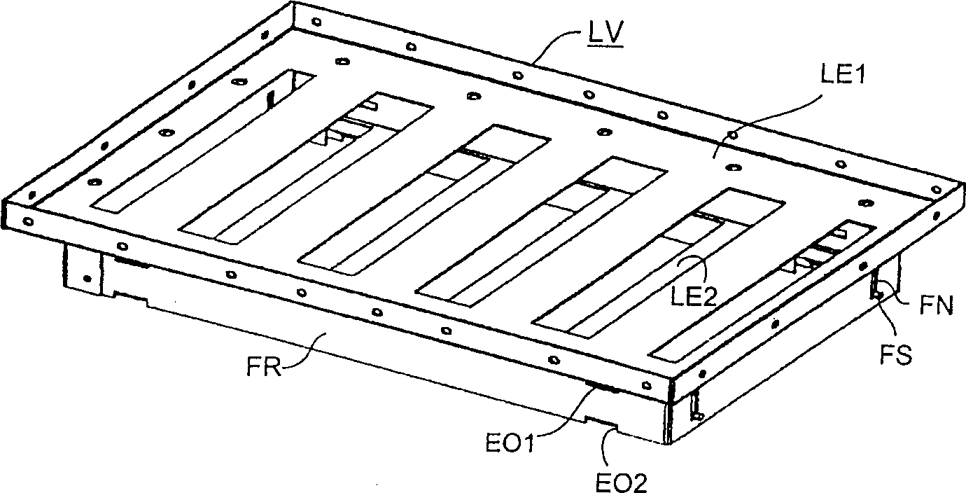
[0021] figure 1 A first embodiment of the ventilation device LV is given, in which a guide frame FR is provided on a fixed ventilation element LE1, which guide frame has guide grooves FN on its end sides and on its long sides There are locking holes EO1, 2 on it. In addition, the movable ventilation element LE2 can be seen in the drawing, which has ventilation gaps, which are arranged offset from the fixed ventilation element LE1 , and are not marked with reference numerals. The entire ventilation device LV is installed in the device in such a way that the side with the movable ventilation element LE2 faces towards the inside of the device. If an overpressure occurs within the switchgear, the movable ventilation element LE2 is pressed against the stationary ventilation element LE1 due to the effect of the pressure wave. The device can be closed in this way by means of a staggered arrangement of the ventilation slots.

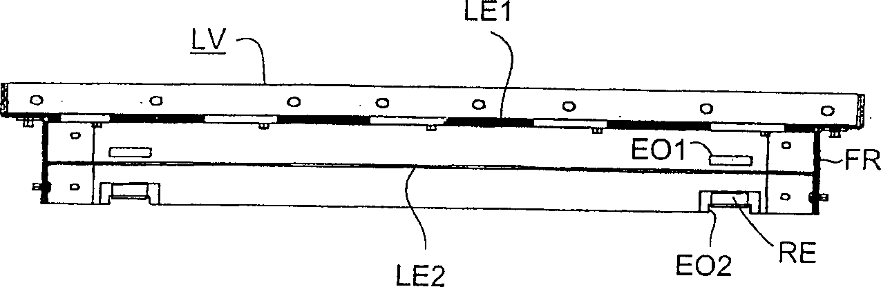
[0022] exist figure 2 In addition to the fixed ventil...


PUM


Abstract

The invention discloses a power switchgear (ES), comprising at least one functional module (FM, FM...) with a closed casing and a pressure relief channel (DK) connected with the casing, wherein the pressure relief The channel (DK) has, on at least one of its outer surfaces, a ventilation device (LV, LV...) consisting of two ventilating parts (LE1, 2) arranged at a distance from one another in front of the other and having ventilation holes (LE1, 2), one of which ( LE1) is fixedly connected with the outer surface of the pressure relief channel (DK), another ventilation part (LE2) can move relative to the fixed ventilation part (LE1), and the movable ventilation part (LE2) can be in a guide frame (FR) moves linearly inside, the ventilation holes of the two ventilation parts (LE1, 2) are staggered to each other, and the movable ventilation part (LE2) has locking holes (EO1, 2) on the guide frame (FR). ) correspondingly provided elastic positioning element (RE). Such switchgear can be used in power supply and distribution installations.

Description

technical field [0001] The invention relates to a power switching device comprising at least one functional module with a closed housing and a pressure relief channel connected to said housing, wherein said pressure relief channel has on at least one of its outer surfaces a The ventilation device is composed of partition-shaped ventilation parts arranged at intervals in front and rear and provided with ventilation holes. One of the ventilation parts is fixedly connected to the outer surface of the pressure relief channel, and the other ventilation part can move relative to the fixed ventilation part. [0002] The present invention also relates to a ventilation device with two partition-shaped ventilation parts arranged at intervals front and rear and provided with ventilation holes, wherein one ventilation part is fixedly connected to the wall of a device to be ventilated, and the other ventilation part can be opposite The fixed ventilation part moves. Background technique ...

Claims


Application Information

Patent Timeline
IPC IPC(8): H02B13/025
CPCH02B13/025H02B1/56
Inventor 马丁·艾塞尔特吉尔多·马恩阿基姆·米尔比奇
Owner SIEMENS AG
Why Eureka
Try Eureka