Method and device for end forming of yarn in jet spinning machine

An open-air spinning machine and a technology for yarn spooling up, which is applied in the field of yarn spooling to achieve the effect of improving the quality of winding yarns

Inactive Publication Date: 2002-12-11
RIETER CZ AS
View PDF2 Cites 12 Cited by
  • Summary
  • Abstract
  • Description
  • Claims
  • Application Information

AI Technical Summary

Problems solved by technology

However, by adjusting the pull-off speed or the winding speed, it is not possible to avoid the formation of loops after spinning-in due to the pull-off of the working mechanism and the slack of the yarn between the winding devices, because the pull-off is fixed non-adjustably by the machine design. speed and winding speed

Method used


Image

  • Method and device for end forming of yarn in jet spinning machine
  • Method and device for end forming of yarn in jet spinning machine
  • Method and device for end forming of yarn in jet spinning machine

Examples


Embodiment Construction

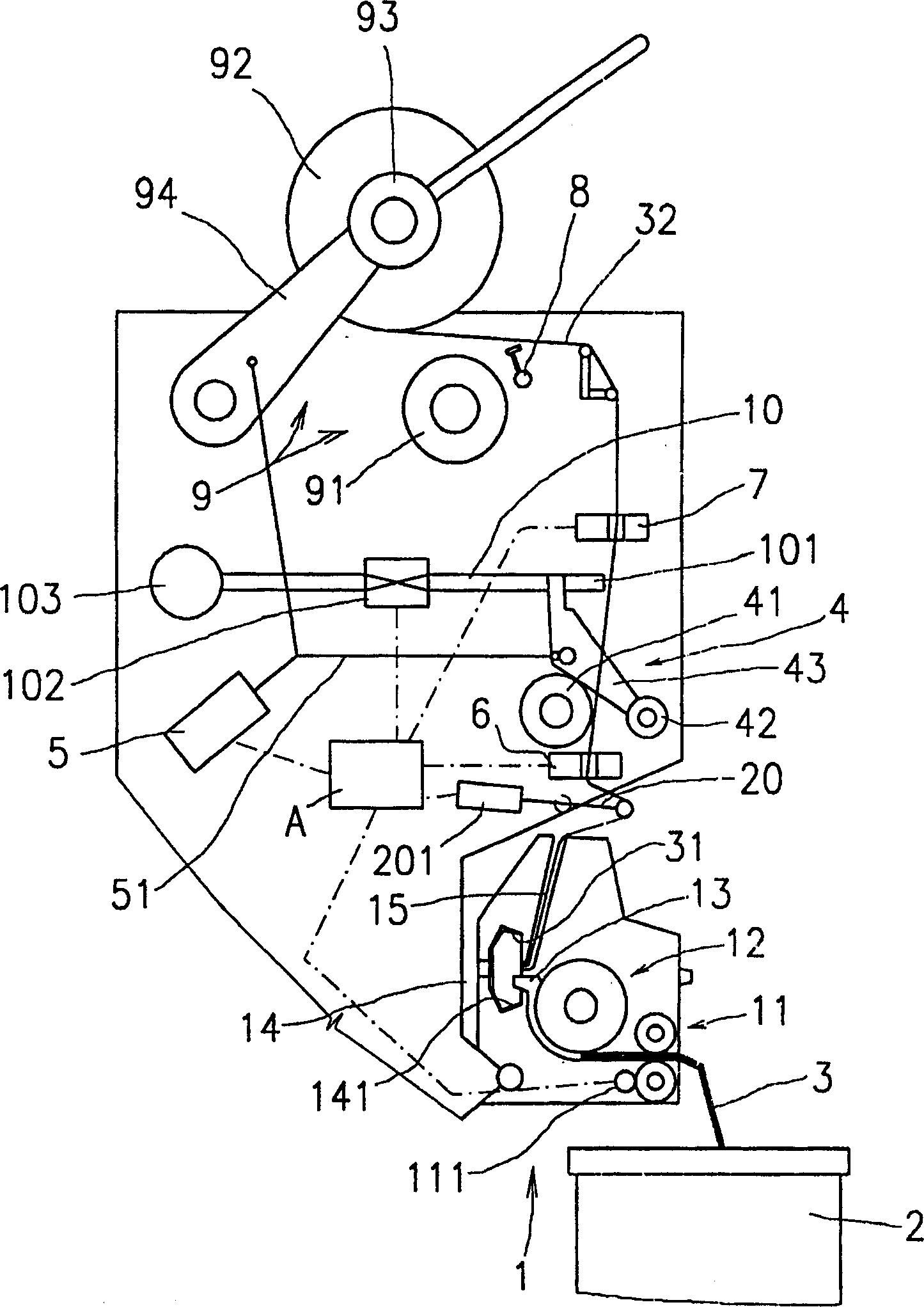
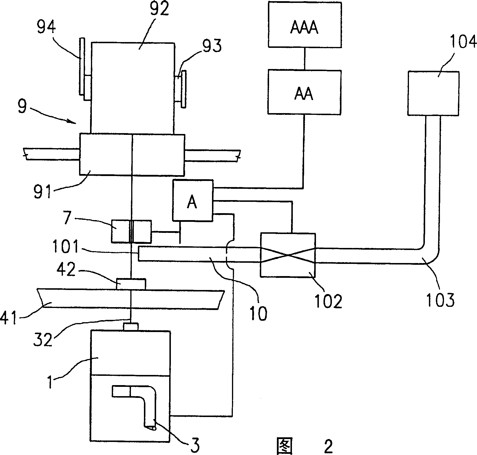
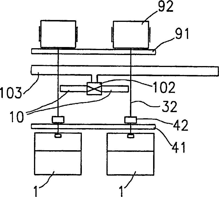
[0018] The air spinning machine includes a plurality of sequentially arranged working mechanisms, each of which is suitable for independently producing yarn from a sliver and winding the produced yarn on a bobbin. The device of the invention is illustrated on the basis of a semi-automatic spinning machine disclosed in patent CZ284295.

[0019] Each working part comprises spinning mechanism 1 and is positioned at below spinning mechanism 1 and the sliver tube 2 that sliver 3 is conveyed in the feeding device 11 of spinning mechanism 1, and feeding device 11 comprises and links to each other with control mechanism A Feed clutch 111. The feeding device 11 is followed by a single-strand withdrawal (singling-out) device 12 for single-strand withdrawal of single fibers from the sliver 3 . The conveying channel 13 of the single-strand extracted fiber entering the inner cavity of the spinning cup 14 is connected with the single-strand drawing device 12, and the widest part of the spi...


PUM


Abstract

A method for spinning-in a yarn on an open-end spinning machine, wherein the yarn (32) between the pulling-off mechanism (4) and the winding device (9) begins to be stressed at the latest at the beginning of pulling-off of the yarn. The negative pressure sucks the yarn (32) coil in the process of entering the negative pressure tube (10) of the working mechanism. After the normal working yarn winding speed is restored, the coils of the yarn (32) in the negative pressure tube (10) are consumed and the negative pressure on the yarn (32) is stopped. This method can be used for all air spinning machines, and also for such devices, the principle of which is that each On the working mechanism, a yarn suction hole (101) of the negative pressure tube (10) for temporarily storing the spun-out yarn (32) after spinning is arranged. The negative pressure tube (10) is a part of the working mechanism of the air spinning machine and is connected to the negative pressure source (1014) in a controllable manner.

Description

technical field [0001] The invention relates to a method for spinning-in yarn on air spinning machines, the steps of yarn and rotor preparation for spinning-in are carried out on these spinning machines equipped with attending devices, and on these spinning machines The yarn and spinning rotor preparation steps are done manually on the machine. [0002] The present invention also relates to a yarn spin-in device on an air spinning machine, comprising a plurality of working mechanisms arranged in sequence, each working mechanism including a yarn producing and spinning mechanism, a yarn pulling away mechanism and a yarn winding device. Background technique [0003] During the spinning-in process of an open-end spinning machine, including inserting the yarn end into the spinning cup, starting the yarn pulling off from the spinning cup, and starting winding, the difference between the yarn pulling-off speed and the winding speed causes In order to prevent the yarn in the part b...

Claims


Application Information

Patent Timeline
Patent Type & Authority Applications(China)
IPC IPC(8): D01H4/50D01H4/48
Inventor J·卢德维彻克J·马克尔
Owner RIETER CZ AS
Why Eureka
Try Eureka