

High-frequency heater
A technology of high-frequency heating device and power supply device, which is applied in microwave heating and other directions, can solve the problems of device influence, current circuit breaker shutdown, and heating of components of high-frequency heating device.
- Summary
- Abstract
- Description
- Claims
- Application Information
AI Technical Summary
Problems solved by technology
Method used
Image

Examples
Embodiment Construction
[0042] Best Mode for Carrying Out the Invention
[0043] Hereinafter, specific implementation devices of the present invention will be described with reference to the accompanying drawings.
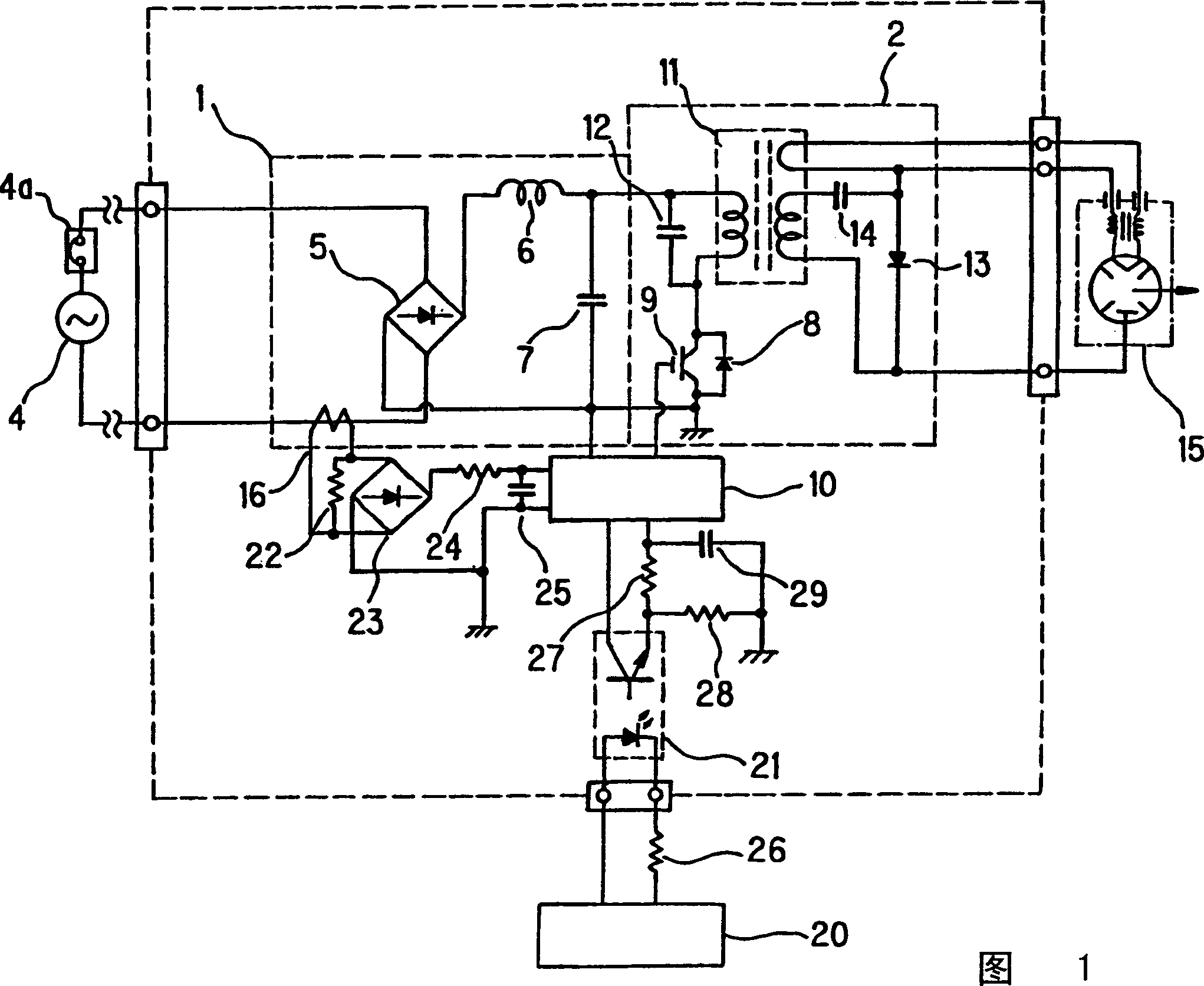
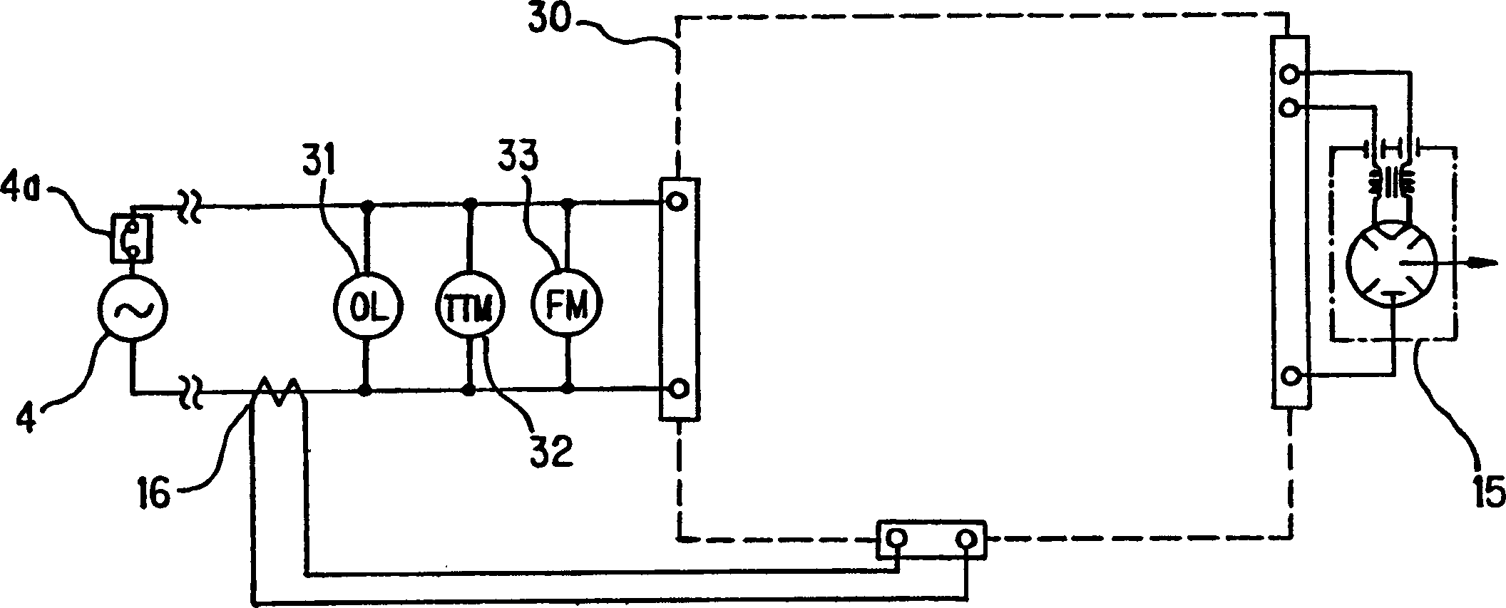
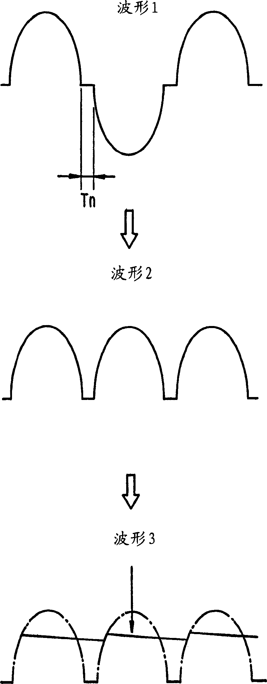
[0044] 1 and 2 show a high-frequency heating device according to an embodiment of the invention. Figure 1, with Figure 7 Like elements in the high-frequency heating device shown (as an example of a magnetron drive circuit) are marked with the same reference numerals. 3 and 4 are schematic diagrams illustrating the input current comparison scheme, FIG. 3 is a waveform diagram related to the input current detector 16, and FIG. 4 is a waveform diagram related to the control circuit 20.
[0045] As shown in Figure 1, the high-frequency heating device of the present embodiment comprises: a power supply unit 1 connected to a civilian power supply 4, an overcurrent circuit breaker 4a is arranged at its incoming line, and the overcurrent circuit breaker is obtained from the power supply 4 Civi...
PUM
 Abstract
Description
Claims
Application Information