Impeller, blower and freezing-cooling storeroom
A technology for refrigerators and impellers, which is applied to mechanical equipment, household refrigeration devices, machines/engines, etc., can solve the problems of deterioration of air supply performance of impeller 1, large airflow turbulence, and increased turbulent sound.
- Summary
- Abstract
- Description
- Claims
- Application Information
AI Technical Summary
Problems solved by technology
Method used
Image

Examples
no. 1 example
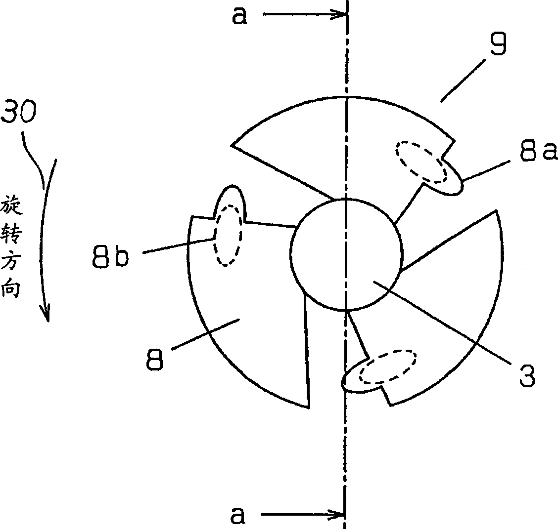
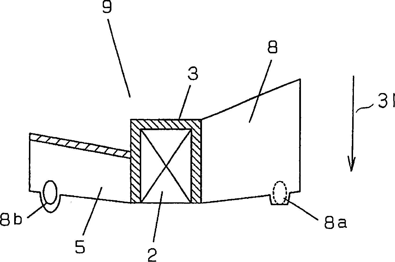
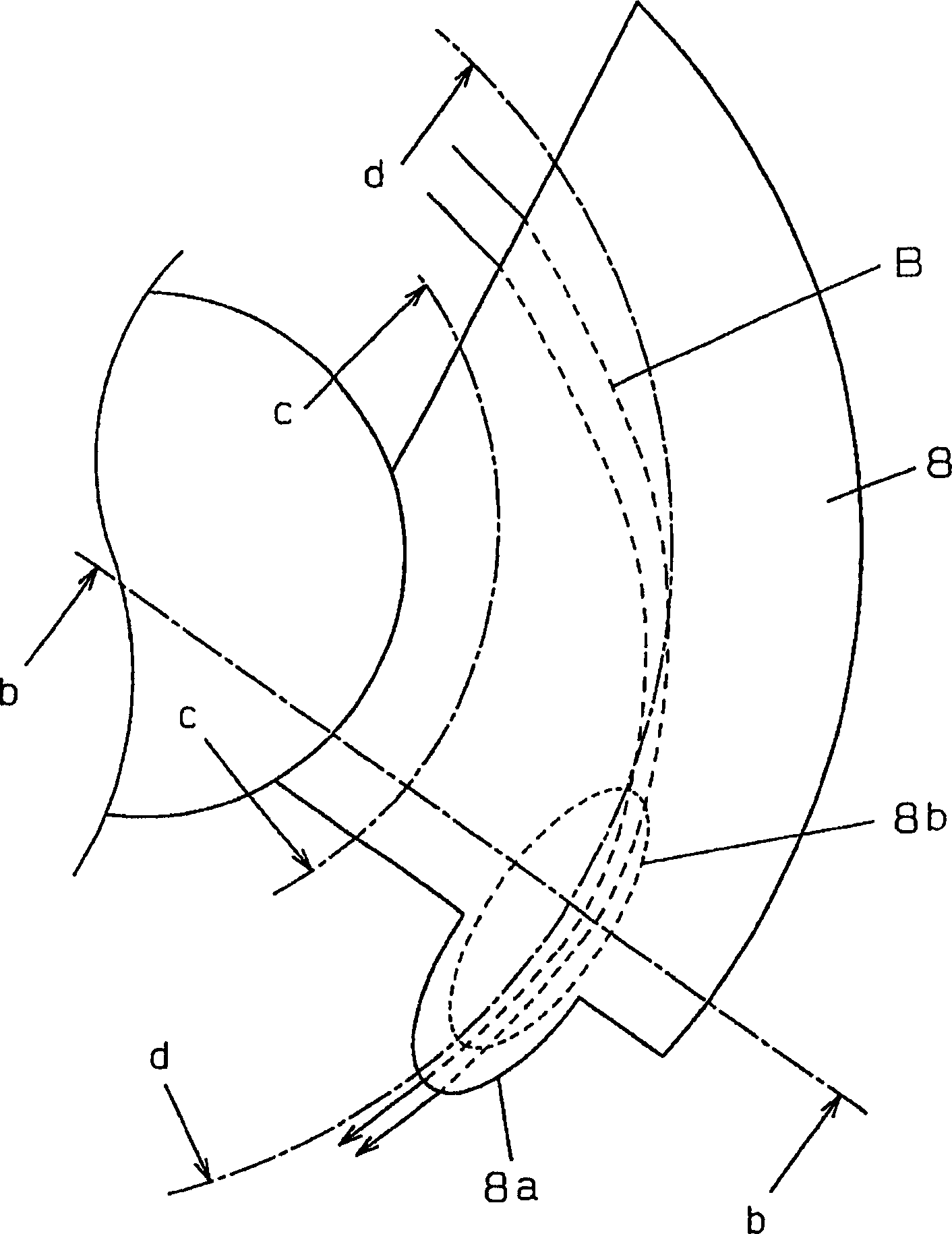
[0037] Figure 1 to Figure 15 The impeller of the first embodiment of the present invention is shown. exist figure 1 , figure 2 Among them, a plurality of blades 8 are arranged around the hub 3 . The convex part (airflow attachment device) 8a is provided on the trailing edge of the blade 8, the concave part (airflow direction changing device) 8b is provided on the pressure surface 5 side of the blade 8, and one end of the concave part 8b extends to the vicinity of the trailing edge of the blade 8. through the impeller figure 1 Turn left as indicated by the middle arrow 30, and the air is directed as figure 2 Axial outflow indicated by arrow 31. When the impeller 9 is set under the condition of large air duct resistance in the refrigerator, if image 3 As shown, the airflow B with a large velocity component in the radial direction passing through the blade 8 is blocked by the concave part 8b, as Figure 4 and Figure 5 The transformations shown are axial. Therefore...
no. 2 example
[0045] Figure 16 An impeller showing a second embodiment of the present invention. The same symbols are used for the same structural parts as those of the previous embodiments, and descriptions thereof are omitted.
[0046] exist Figure 16 Among them, one end of the concave portion 8b extends to the front end of the convex portion 8a. According to this structure, the airflow F having a large radial velocity component passing through the impeller 9 is blocked by the concave portion 8b on the pressure surface 5 side and transformed into an axial airflow, and flows out from the pressure surface 5 side. By providing the convex portion 8a at the trailing edge of the blade 8 and partially extending the chord length of the blade to suppress the separation of the airflow D on the side of the negative pressure surface 7, the airflow flowing out from the side of the negative pressure surface 7 and the airflow in the axial direction The turbulence generated at the time of merging is...
no. 3 example
[0048] Figure 17 ~ Figure 20 A blower 16 according to a third embodiment of the present invention is shown. The same symbols are used for the same structural parts as those of the previous embodiments, and descriptions thereof are omitted.
[0049] exist Figure 17 , Figure 18 Among them, the outer wall 12 of the blower 16 surrounds two plate-shaped inlet and outlet flanges that divide the suction side and the exhaust side of the blade 8, that is, the outer peripheral edges of the first inlet and outlet flanges 10 and the second inlet and outlet flanges 11 . The swirling flow circulation space 14 between the first inlet and outlet flanges 10 and the second inlet and outlet flanges 11 has an opening 13 facing the blade 8 . A plurality of columns 15 a, 15 b provided in the swirling flow circulation space 14 extend substantially in the radial direction of the blade 8 from the opening edges of the first inlet and outlet flanges 10 and the second inlet and outlet flanges 11 . ...
PUM
 Abstract
Description
Claims
Application Information
 - R&D
- Intellectual Property
- Life Sciences
- Materials
- Tech Scout
- Unparalleled Data Quality
- Higher Quality Content
- 60% Fewer Hallucinations
Browse by: Latest US Patents, China's latest patents, Technical Efficacy Thesaurus, Application Domain, Technology Topic, Popular Technical Reports.
© 2025 PatSnap. All rights reserved.Legal|Privacy policy|Modern Slavery Act Transparency Statement|Sitemap|About US| Contact US: help@patsnap.com