Heat exchanger flow circuit arranging method and device

A layout method and heat exchanger technology, which is applied in heat transfer modification, heat exchange equipment, lighting and heating equipment, etc., can solve the problems of heat flow layout without using the field synergy principle, lack of comprehensive consideration, etc., and achieve volume reduction , cost reduction, obvious effect

Inactive Publication Date: 2003-01-08
XI AN JIAOTONG UNIV
View PDF0 Cites 22 Cited by
  • Summary
  • Abstract
  • Description
  • Claims
  • Application Information

AI Technical Summary

Problems solved by technology

To sum up, the disadvantages of the above-mentioned various layout methods are: they often only consider the problem from a single point of view (such as strengthening heat transfer), lack of comprehensive consideration, and do not use the principle of field synergy and the idea of ​​​​equal heat flow layout

Method used


Image

  • Heat exchanger flow circuit arranging method and device
  • Heat exchanger flow circuit arranging method and device
  • Heat exchanger flow circuit arranging method and device

Examples


Embodiment Construction

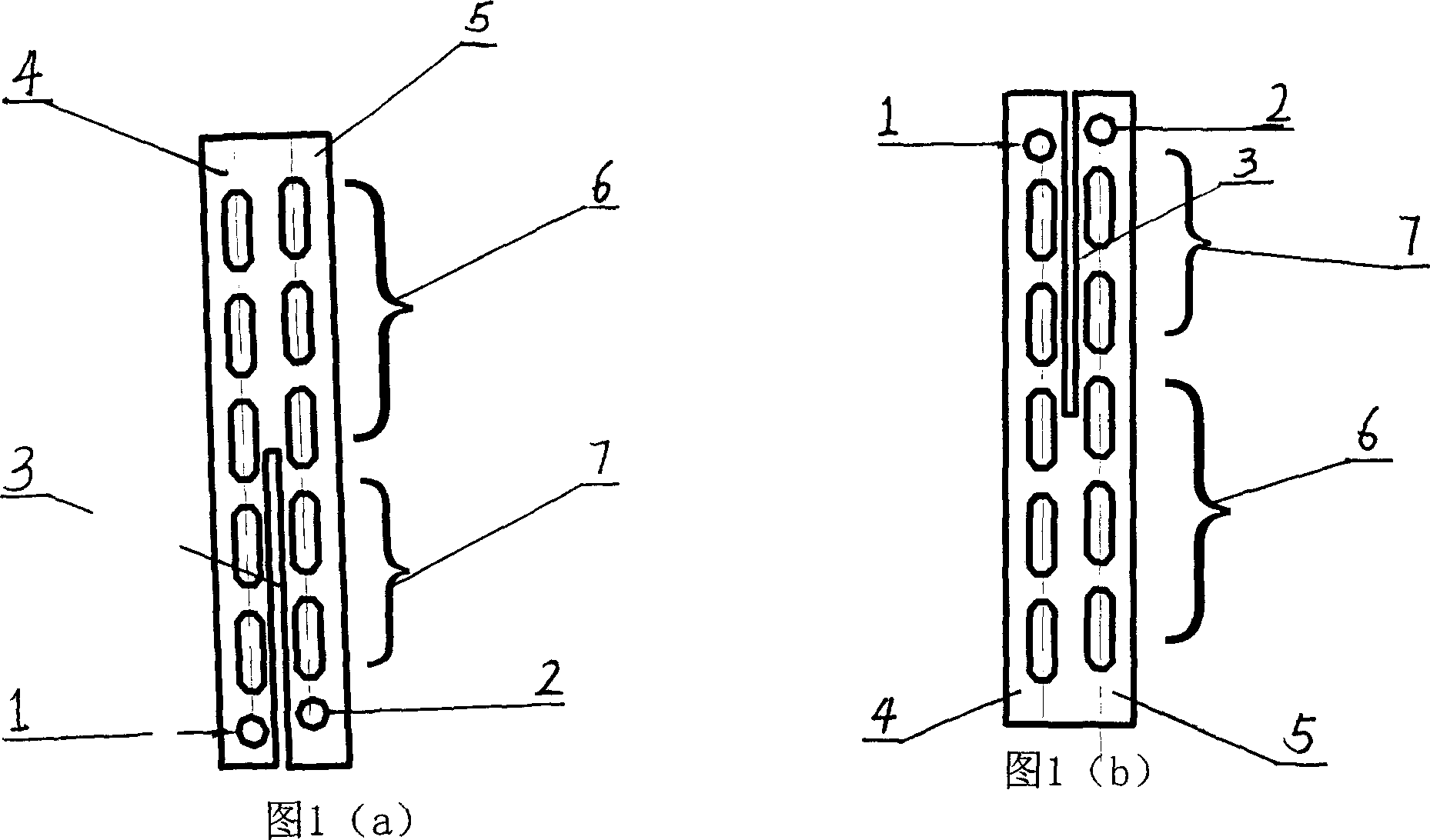
[0023] see figure 1 , the flow path arrangement method of the present invention is as follows:

[0024] 1) Pure countercurrent arrangement

[0025] According to the basic principle of heat transfer, under the same inlet and outlet temperature conditions, the average temperature and pressure of countercurrent flow is the largest, and the average temperature and pressure of downstream flow is the smallest. Therefore, at the same temperature of the hot and cold fluids, the countercurrent arrangement is better than the forward flow arrangement, that is, the flow direction of the refrigerant is opposite to the flow direction of the air;

[0026] 2) Prevent reverse heat conduction in fins

[0027] The inlet and outlet of the refrigerant are both at one end of the heat exchanger, where there is a large temperature difference in the fins, and reverse heat conduction will inevitably occur. In order to avoid reverse heat conduction, the method adopted is to slit the middle part of th...


PUM


Abstract

This invention relates to a design method for the flow circuit of a heat exchanger, which is suitable to the condenser and evaporator in refrigerator or air conditioner using single or mixed refrigerant. In said design multiple factors are comprehensively considered, such as constant heat flow principle and field coordination principle. It is provided that as the phase state of the refrigerant running in tube changes, the flow path number, the type of the fin out of tube and the reinforcing structure in tube should be changed, and suitable nodes should be selected to branch or interflow the flow. The heat exchange characteristic of refrigerating and air conditioning apparatus can be obviously raised.

Description

1. Technical field [0001] The invention relates to a refrigeration equipment and an air conditioner heat exchanger using single and mixed refrigerants, in particular to a flow path arrangement method and device for the heat exchanger. 2. Background technology [0002] In the past, when people increased the heat transfer coefficient of the heat exchanger, they focused more on changing the fin type and the internal structure of the heat exchange tube. The type of fins has developed from the original flat sheet to the current corrugated sheet, "X" type slotted sheet, etc., and the inner structure of the tube has developed from the original light pipe to the current two-dimensional threaded pipe, and even three-dimensional threaded pipe. These measures have obvious effects on improving the heat transfer coefficient. The commonly used small air-conditioning heat exchangers (double-row tube heat exchangers) generally adopt the following flow path arrangements: "Z" shaped flow pat...

Claims


Application Information

Patent Timeline
Patent Type & Authority Applications(China)
IPC IPC(8): F28F13/02
Inventor 陶文铨何雅玲郭进军
Owner XI AN JIAOTONG UNIV
Why Eureka
Try Eureka