Charging rate regulator circuit of battery

A technology to adjust the circuit and charging rate, which is applied in the direction of secondary battery charging/discharging, battery circuit device, charge equalization circuit, etc., and can solve the problem that the battery module capacity becomes zero.

Inactive Publication Date: 2003-02-12
SANYO ELECTRIC CO LTD
View PDF2 Cites 10 Cited by
  • Summary
  • Abstract
  • Description
  • Claims
  • Application Information

AI Technical Summary

Problems solved by technology

[0011] However, due to the Image 6 In the circuit, it is presupposed that commands to the first photocoupler (55) and the second photocoupler (56) are regularly input, so for example, when the power supply to the control system is stopped for maintenance, etc., Since there is no need to input a signal for stopping the flip-flop circuit (9), there is a problem that the discharge continues until the capacity of the battery module (11) becomes substantially zero

Method used


Image

  • Charging rate regulator circuit of battery
  • Charging rate regulator circuit of battery
  • Charging rate regulator circuit of battery

Examples


no. 1 Embodiment

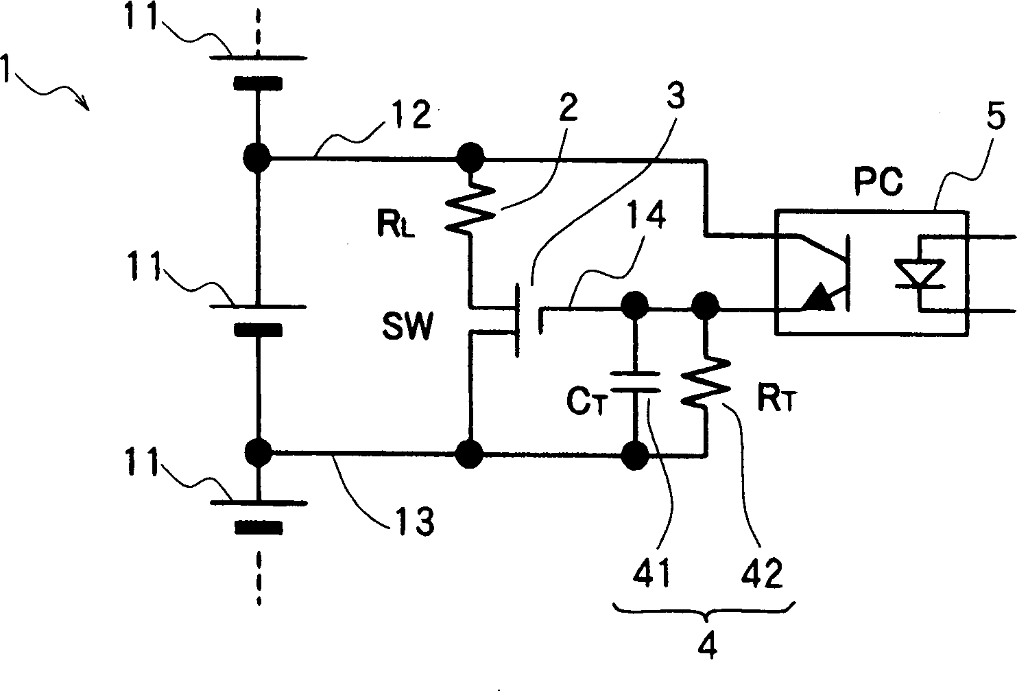
[0030] Such as figure 1 As shown, the charging rate adjustment circuit of the battery pack of this embodiment is aimed at the battery pack (1) formed by connecting battery modules (11) composed of a plurality of storage batteries in series, and according to the direction from the control system (not shown) A discharge command supplied from a specific battery module (11) discharges the battery module (11).

[0031] A pair of discharge lines (12) (13) are drawn from the two poles of each battery module (11), and a discharge resistor (2) with a relatively low resistance value and an on-off switch (3) composed of MOSFETs are interposed between the two discharge lines (12) ) (13), since the on-off switch (3) is closed, the current flows from the battery module (11) to the discharge resistor (2), constituting a discharge circuit for discharging the battery module (11). Connect the secondary side of the optocoupler (5) with a discharge line (12) and a control signal line (14) exten...

no. 2 Embodiment

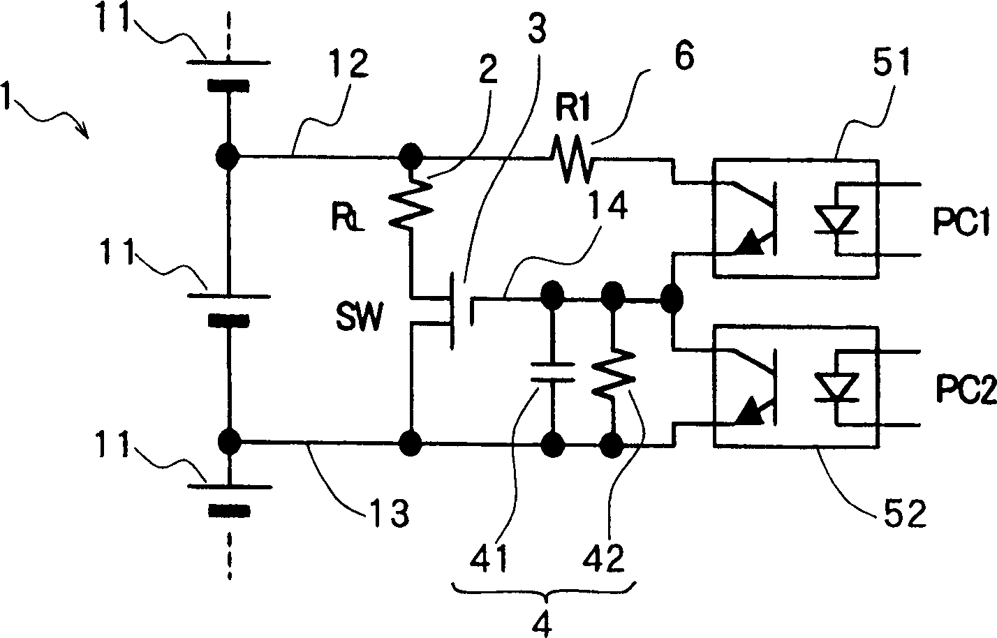
[0038] Such as figure 2 As shown, the charging rate adjustment circuit of the battery pack of this embodiment is a circuit that improves the charging rate adjustment circuit of the first embodiment, and the first optocoupler (51) for closing the on-off switch (3) is connected to the Between one discharge line (12) and the control signal line (14), at the same time connect the second optocoupler (52) for disconnecting the on-off switch (3) between the control signal line (14) and the other discharge line (14). Between lines (13). Furthermore, a short-circuit prevention resistor (6) is interposed on a discharge line (12).

[0039] According to this charging rate adjustment circuit, the on-off switch (3) can be closed according to the discharge command to the first optocoupler (51), so that the battery module (11) can start discharging, and at the same time, the discharge command to the second optocoupler can be The discharge stop instruction of (52) turns off the on-off switc...

no. 3 Embodiment

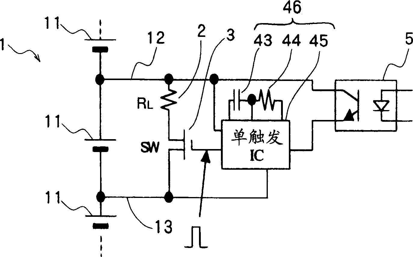
[0042] Such as image 3 As shown, the charging rate adjustment circuit of the battery pack of this embodiment is equipped with a time limit holding circuit (46) with a burst trigger IC (45) to replace the time limit holding circuit (4) composed of a CR circuit in the first embodiment. , capacitor (43) and resistance (44) are connected with impulse trigger IC (45).

[0043] When the discharge command ("high") is input from the control system (not shown) to the primary side of a specific optocoupler (5), the secondary side of the optocoupler (5) is turned on, and the time limit holding circuit The breath trigger IC (45) of (46) supplies the trigger signal, and the breath trigger IC (45) generates corresponding to the time constant determined by the capacitor (43) and resistance (44) accordingly, within a certain period of time is " High" control pulse and apply it to the gate of the on-off switch (3). Thus, the on-off switch (3) is closed within the above-mentioned certain tim...


PUM


Abstract

The invention provides a charging rate adjusting circuit for a cell combination 1 comprising cell modules 11 each comprising one or a plurality of cells and connected in series and adapted to uniformize the cell modules 11 in charging rate. The adjusting circuit comprises a pair of discharge lines 12, 13 extending from opposite electrodes of each cell module 11, a discharge resistor 2 and an on-off switch 3 provided between the discharge lines 12, 13, a timer circuit 4 comprising a CR circuit for feeding a control signal to a gate of the on-off switch 3, and a photocoupler 5 for initiating the circuit 4 into operation in response to a discharge command.

Description

technical field [0001] The present invention relates to a circuit for adjusting the charge rate of a plurality of batteries constituting a high-voltage battery pack used as a power source for a running motor in a battery car such as a hybrid car. Background technique [0002] Conventionally, battery packs composed of a plurality of storage batteries connected in series are mounted as power sources for running motors in battery-powered vehicles such as hybrid vehicles. Usually, since a high voltage of 200 to 300 volts needs to be generated in such a battery pack, for example, 60 to 80 units of lithium batteries each outputting about 3.6 volts are connected in series, or each of about 200 units is connected in series. NiMH-based storage batteries with a unit output of about 1.2 volts are connected in series to form a battery pack. [0003] It is desirable that in such a battery pack, the states of charge of all the batteries are equalized. For example, if one storage battery...

Claims


Application Information

Patent Timeline
Patent Type & Authority Applications(China)
IPC IPC(8): B60L11/18H01M10/44H02J7/00
CPCY02T10/7055H02J7/0016Y02T10/70
Inventor 古川公彦
Owner SANYO ELECTRIC CO LTD
Why Eureka
Try Eureka