Fuel oil pump

A technology of fuel pump and fuel oil, which is applied in the direction of pumps, pump devices, pump components, etc., which can solve the problems of increased time and cost, increased manufacturing cost of fuel pumps, etc., to reduce machining costs, ensure dimensional accuracy, and ensure accurate concentricity degree of effect

Inactive Publication Date: 2003-03-05
DENSO CORP
View PDF0 Cites 4 Cited by
  • Summary
  • Abstract
  • Description
  • Claims
  • Application Information

AI Technical Summary

Problems solved by technology

Therefore, the time and cost associated with machining the support member 16 can increase, and the overall manufacturing cost of the fuel pump can increase

Method used


Image

  • Fuel oil pump
  • Fuel oil pump
  • Fuel oil pump

Examples


no. 1 approach

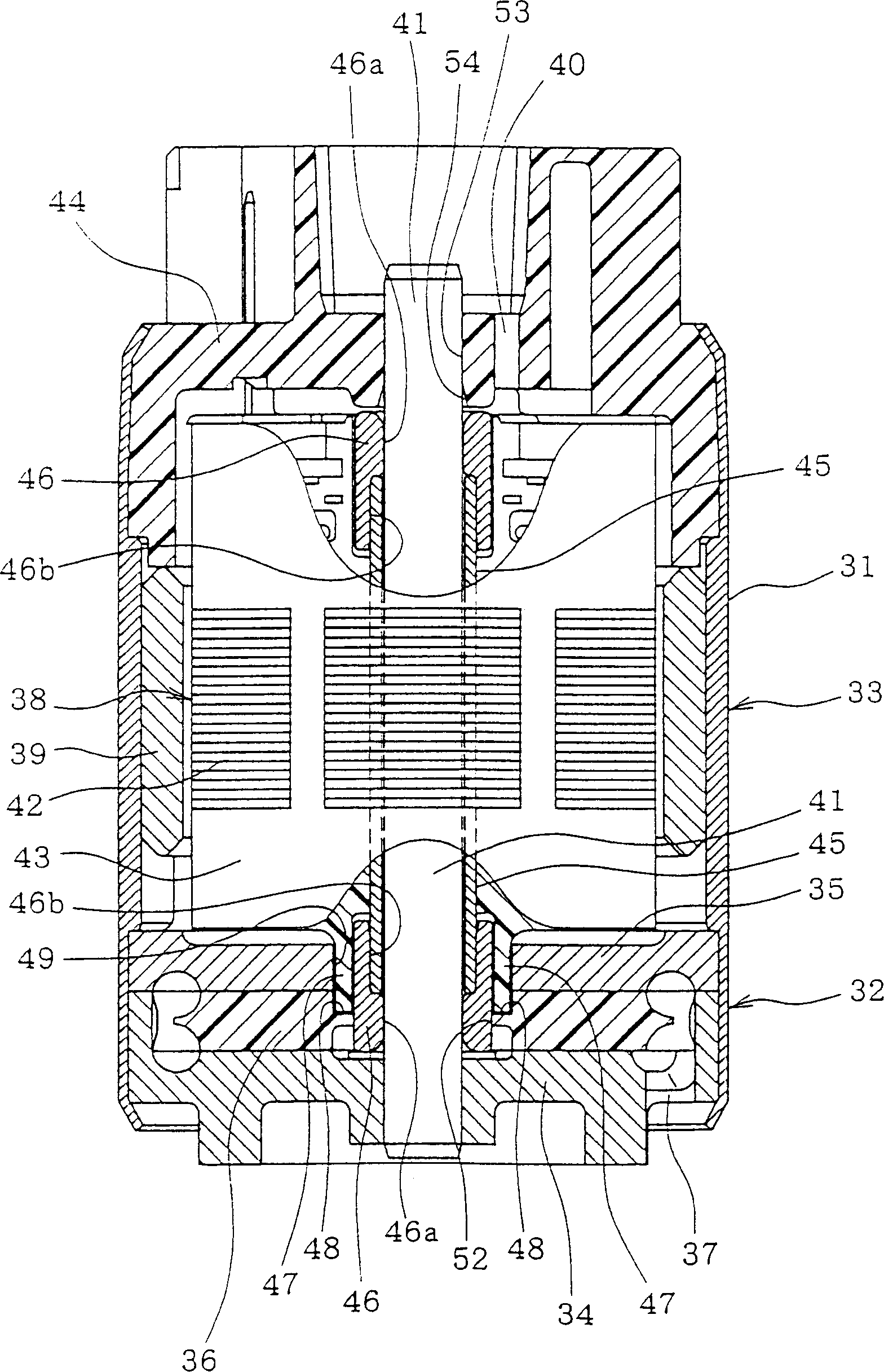
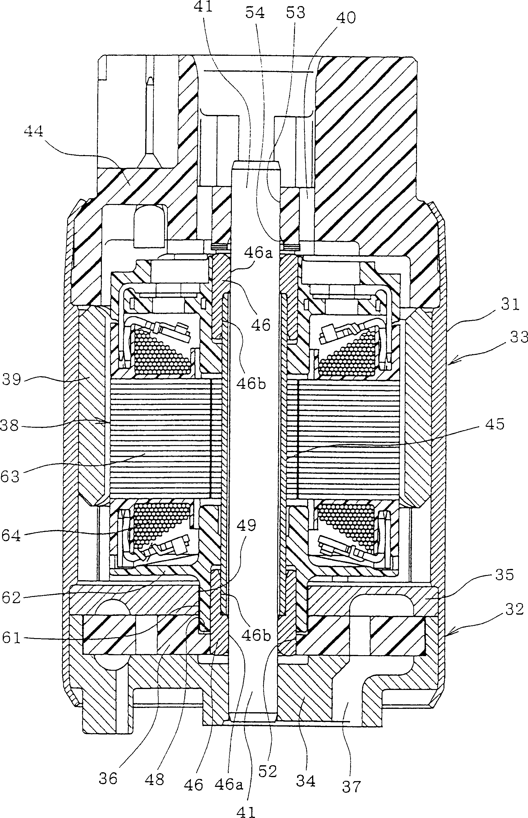
[0024] The following will be based on figure 1 and figure 2 The first embodiment of the present invention will be described. First, briefly explain the overall structure of the fuel pump. The pump unit 32 and the motor unit 33 are arranged in the axial direction, and are installed in the cylindrical housing 31 of the fuel pump. The pump unit 32 is constructed such that metal or resin pump casings 34 and 35 are fixed on the bottom end of the casing 31 by caulking or the like, and resin or metal impellers 36 (rotors) are stored in the pump casings 34 and 35 . A fuel suction (suction) port 37 is formed on the lower pump casing 34 . Fuel in a fuel container (not shown) is sucked into the pump housings 34 and 35 through a fuel suction port 37 . Fuel discharged from a discharge port (not shown) formed on the upper pump housing 35 is discharged from the fuel discharge port 40 after passing through a gap formed between the armature 38 and the magnet 39 of the motor unit 33 .

...


PUM


Abstract

A pipe member is pushed into an inner periphery of a core of an armature to fix the pipe member to the armature. The pipe member is inserted over a fixed shaft. Bearing members have a small hole and a large hole formed at their centers. Pipe member ends are pushed into and fixed to the large diameter holes. The fixed shaft is inserted into the small holes to rotatably support the armature. A guide hole is formed at the center of an impeller of a pump unit, and is fitted to the bearing member, thereby the impeller rotates while the impeller is guided by the outer peripheral surface of the bearing member which rotates integrally with the armature. Coupling protrusions formed on the armature are inserted, and engaged with engagement recesses formed in the impeller to transmit a rotation force of the armature to the impeller.

Description

technical field [0001] The present invention relates to a fuel pump which is constructed such that a fixed shaft is located at the center of a casing, and a motor unit and a pump unit rotate around the fixed shaft. Background technique [0002] Japanese Patent Laid-Open No. Sho. 43-82086 discloses a fuel pump. Generally speaking, in this fuel pump, as in Figure 4 As shown in , the fixed shaft 12 is fixed on the inner circumference of both ends of the pipe member 15 at the center of the housing 11. The supporting member 16 is individually pushed and fixed at the center of the armature 14 (rotor) provided to the motor unit 13 . These support members 16 are rotatably inserted on the fixed shaft 12 to rotatably support the pipe member 15 with the fixed shaft 12 through the support members 16 . In this case, the support member 16 is pushed and fixed on the inner circumference of the pipe member 15 so that the support member 16 is fixed between the pipe member 15 and the fixed ...

Claims


Application Information

Patent Timeline
Patent Type & Authority Applications(China)
IPC IPC(8): F02M37/04F02M37/08F04D5/00F04D29/043F04D29/42
CPCF02M37/04F02M37/08
Inventor 岩成荣二酒井博美
Owner DENSO CORP
Why Eureka
Try Eureka