
Automatic high-efficiency energy-saving cooking vessel

A technology of cookware and automatic mode, applied in the direction of home utensils, kitchen utensils, cooking utensils, etc.

Inactive Publication Date: 2003-03-12
吴炯明 +1
View PDF10 Cites 12 Cited by
  • Summary
  • Abstract
  • Description
  • Claims
  • Application Information

AI Technical Summary

Problems solved by technology

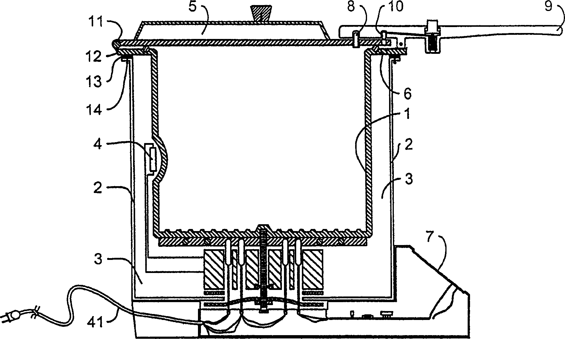
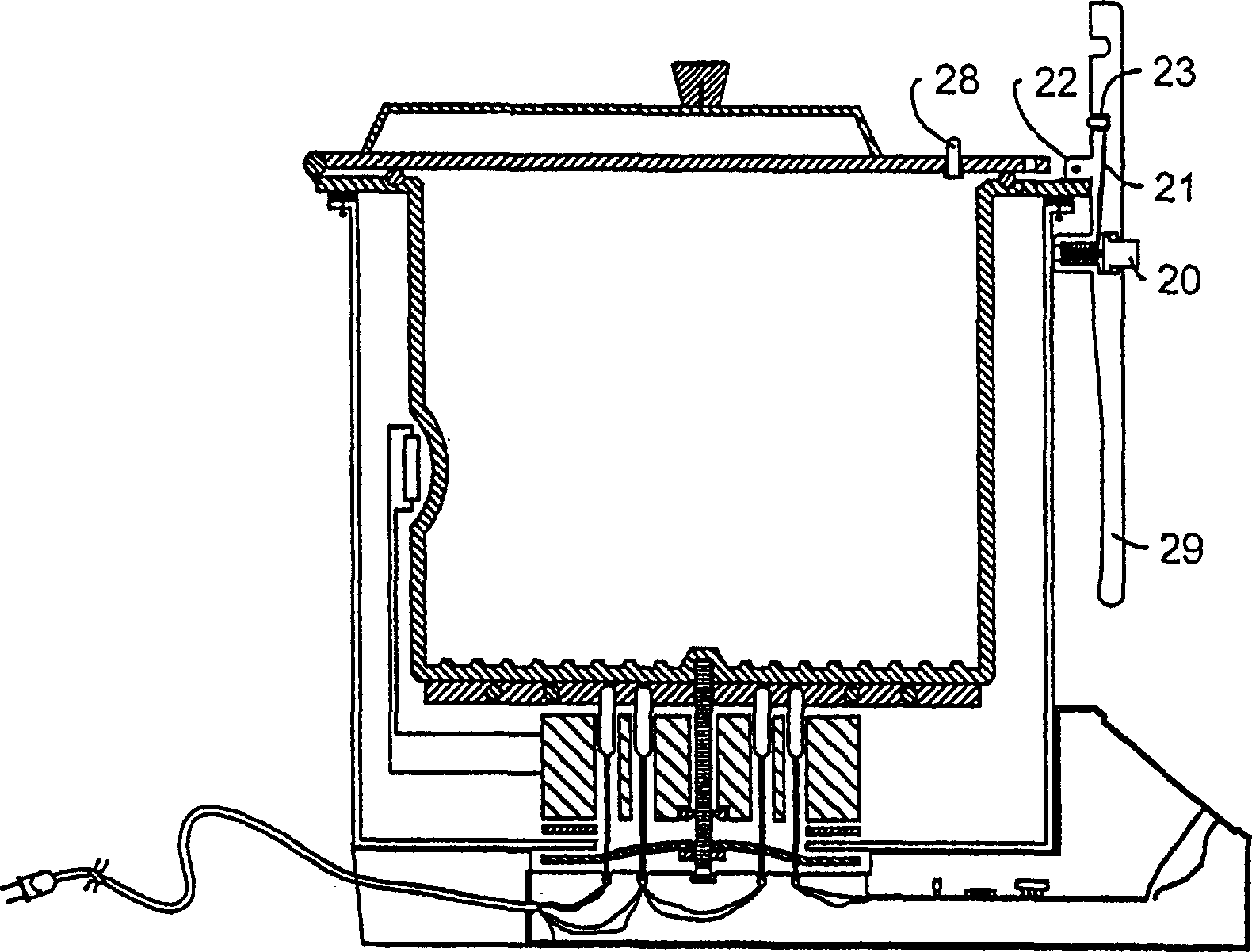
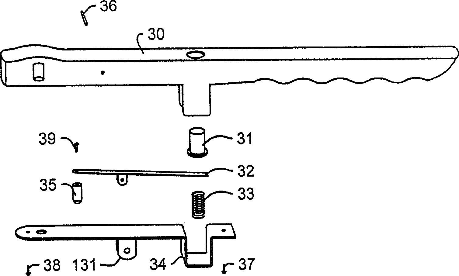
None of the electronic pressure vessels above have the new style steamer style handle to securely latch the cooker

Method used


Image

  • Automatic high-efficiency energy-saving cooking vessel
  • Automatic high-efficiency energy-saving cooking vessel
  • Automatic high-efficiency energy-saving cooking vessel

Examples


Embodiment Construction

[0038] Before the disclosed embodiments of the invention are explained in detail, it is to be understood that the invention is not limited in application to the specific structural details shown, as the invention also has other embodiments. Also, the terminology used herein is for the purpose of description and not limitation.

[0039]Generally, pressure cookers are designed to seal and control the steam that is generated when the water inside the cooker begins to boil. Thus, pressure cookers are constructed of strong and durable materials, such as stainless steel and heavy gauge aluminum, to safely withstand high pressures and temperatures. Pressure cookers also operate at temperatures within the pressure design limits and within their heating and cooling capabilities to affect the characteristics of the food. For example, the design pressure limit is generally one or half an atmospheric pressure unit above ambient pressure. Atmospheric or ambient pressure is 14.7 pounds pe...


PUM


Abstract

An energy-saving autoamtic pressure cooker is characterized by that its thermally insulating cooking container has a bottom supporter to prevent its bottom is adhered by food, its unique handle allows single hand operation to seal or open the container, and its built-in modern is used for remote control by telephone or computer or programmable cooking. Its energy-saving cooking mode is characterized by that after the food is heated to 120 deg.C the heating is stopped and the food is done by the latent heat.

Description

technical field [0001] The present invention relates to pressure cookers, and more particularly, to electronic pressure cookers with an adiabatic cooking mode that can be remotely controlled. Background technique [0002] The principle of cooking food by steam pressure has been known at least since 1679, when a French physicist, Denis Papin, invented the "Papin cooker", a steamer with an airtight lid with a safety valve, as described in The New British Encyclopedia "in the 15th edition, volume 9 (1993) page 686 described. In 1939, the steamer-type pressure cooker was introduced into mass production by National Presto Industries and became a method of preparing food in a third of the time while maintaining the vitamin and mineral content of the food and preserving the aroma and color of the food popular method. [0003] Many cookers, including this European invention, are used to cook food in a third to a tenth of the normal time. At the height ...

Claims


Application Information

Patent Timeline
IPC IPC(8): A47J27/086
Inventor 吴炯明吴咏棠
Owner 吴炯明
Learn More