Bearing device for wheel

A bearing device and wheel technology, applied in the directions of bearings, axles, wheels, etc., can solve the problems such as the deterioration of the vibration accuracy of the side of the wheel mounting flange 581, and achieve the effect of reducing the operation process.

Inactive Publication Date: 2003-04-02
NTN CORP
View PDF2 Cites 13 Cited by
  • Summary
  • Abstract
  • Description
  • Claims
  • Application Information

AI Technical Summary

Problems solved by technology

Therefore, it is difficult to predict or set this kind of deformation amount and error according to fastening conditions, etc., so that the vibration accuracy of the side surface of the wheel mounting flange 581 will be further deteriorated in the end.

Method used


Image

  • Bearing device for wheel
  • Bearing device for wheel
  • Bearing device for wheel

Examples


Embodiment Construction

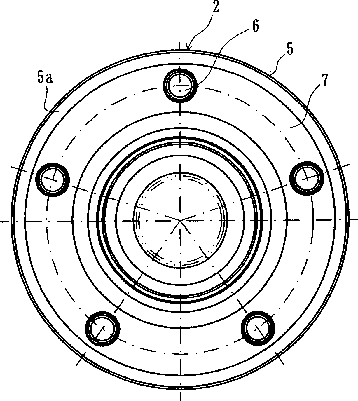
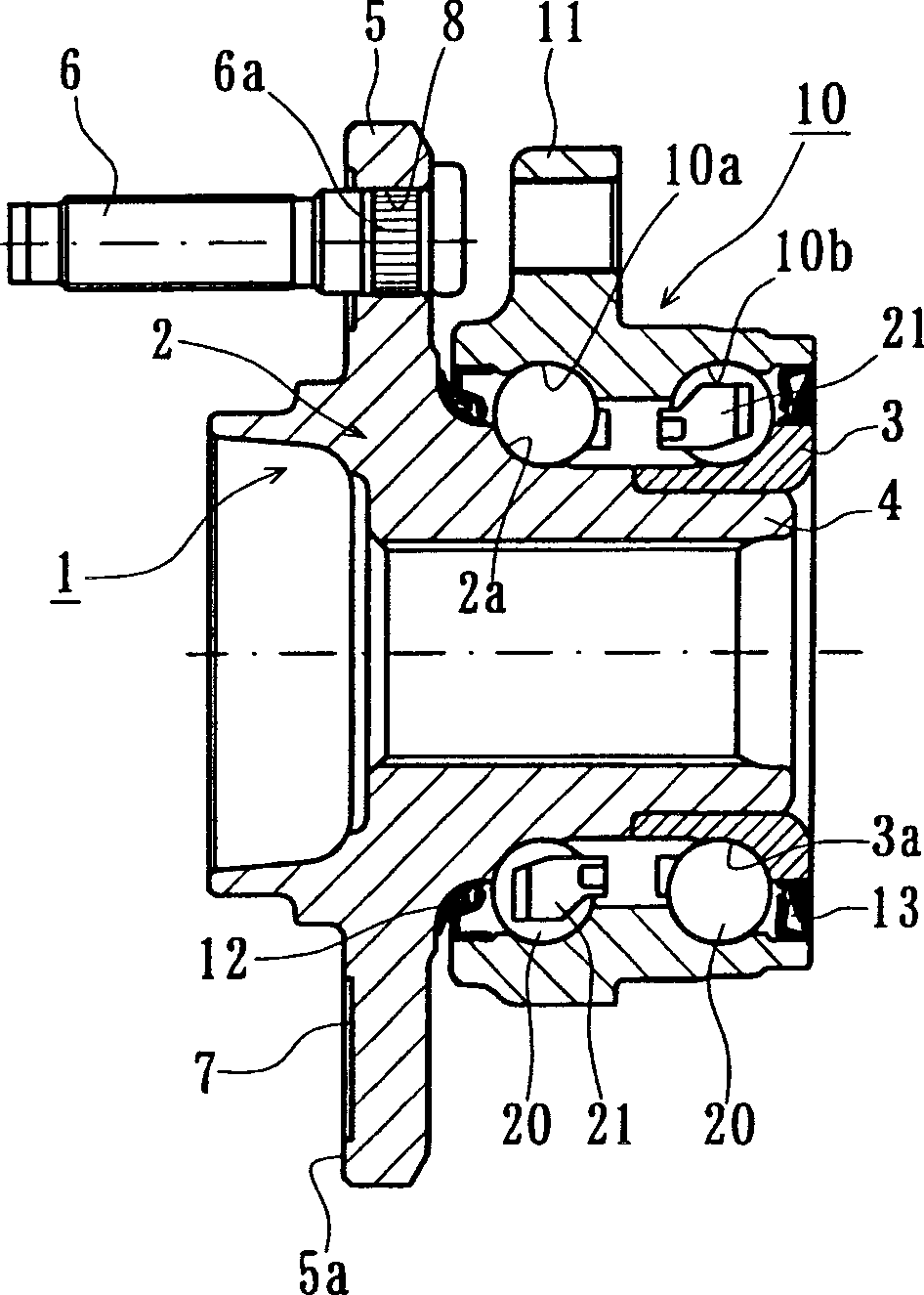
[0074] Embodiments of the present invention will be described in detail below with reference to the accompanying drawings. Fig. 1 shows a first embodiment of a bearing device for a wheel according to the present invention, (b) is a longitudinal sectional view, and (a) is a side view thereof.

[0075] This bearing device for a wheel has an inner member 1 , an outer member 10 and a plurality of rows of rolling bodies 20 , 20 . The inner part 1 is composed of a hub 2 and an inner wheel 3 . The inner ring 3 is press-fitted into a small-diameter stepped portion 4 formed at the inner end portion of the hub 2 . In addition, an inner inner rotational surface 3 a is formed on an inner inner rotational surface 2 a inside the outer circumference of the hub 2 and an inner inner rotational surface 3 a on the outer circumference of the inner ring 3 . In addition, a wheel mounting flange 5 for mounting a wheel (omitted in the figure) is integrally formed on the outer end of the hub 2, and ...


PUM


Abstract

A bearing apparatus for a wheel is provided to improve the surface runout precision of the brake rotor side of a bearing apparatus. A bearing apparatus for a wheel consists of: a rolling bearing for rotatably supporting a wheel relative to a body of vehicle; double row rolling elements (20) arranged between an inner member (1) and an outer member (10); a wheel mounting flange (5) for fastening the wheel on a hub wheel (2); and an annular groove (7) formed on the wheel mounting flange and having a predetermined width including a hub bolt (6). Side surface, excepting the annular groove (7) part, of the wheel mounting flange (5) is formed as a cut-finished surface which is done after the hub bolt (6) is press-fitted into the wheel mounting flange (5).

Description

technical field [0001] The present invention relates to a bearing device for a wheel supporting a wheel of an automobile etc., in particular to a bearing device for a wheel which improves the vibration accuracy of the end surface of the flange on which the wheel is mounted and can suppress strong vibrations generated during braking. Background technique [0002] In general, contrary to the increasing popularity of disc brakes with excellent braking performance, when the disc brake rotor is clamped by the brake pads for braking, vibration will be generated when braking a vehicle running at a low speed, causing Screeching noise with very low frequency. This phenomenon is usually called strong vibration caused by braking. With the requirement of high performance and low noise of the vehicle, analyzing and improving this phenomenon has been paid more and more attention as a new technical subject. [0003] Although the mechanical principle of this strong vibration phenomenon has...

Claims


Application Information

Patent Timeline
Patent Type & Authority Applications(China)
IPC IPC(8): F16C19/00B60B27/00F16D65/12
CPCF16D65/123B60B27/0094B60B27/0042B60B27/0005B60B27/00Y02T10/86B60B27/0084F16C2326/02F16C35/06F16C43/04F16C19/185F16C19/186F16C19/187F16C19/00
Inventor 梅木田光山本一成田岛英児小仓博幸福岛茂明小泽仁博
Owner NTN CORP
Why Eureka
Try Eureka