Two-way optical fiber dispersion compensation device

A dispersion compensation, bidirectional fiber technology, applied in the coupling of optical waveguides, electromagnetic wave transmission systems, electrical components, etc., can solve the problems of difficulty, high manufacturing process requirements, and low utilization rate of dispersion compensation fibers, and achieves improved utilization, The effect of improving utilization

Inactive Publication Date: 2003-04-23
HUAWEI TECH CO LTD
View PDF0 Cites 3 Cited by
  • Summary
  • Abstract
  • Description
  • Claims
  • Application Information

AI Technical Summary

Problems solved by technology

However, its disadvantage is that the improvement of the optical fiber dispersion coefficient needs to be obtained by increasing the waveguide dispersion of the optical fiber, which has high requirements on the refractive index distribution of the material. Although it can be realized in theory, it requires high manufacturing processes and is difficult. The method of dispersion coefficient has low utilization rate of dispersion compensating fiber
In addition, this simple optical fiber dispersion compensation device can only be applied to single-fiber one-way optical fiber transmission systems. For single-fiber bidirectional and dual-fiber bidirectional optical fiber transmission systems, multiple dispersion compensation devices are required to meet the dispersion compensation requirements.

Method used


Image

  • Two-way optical fiber dispersion compensation device
  • Two-way optical fiber dispersion compensation device
  • Two-way optical fiber dispersion compensation device

Examples


Embodiment Construction

[0013] The present invention will be described in detail below in conjunction with the accompanying drawings and embodiments.

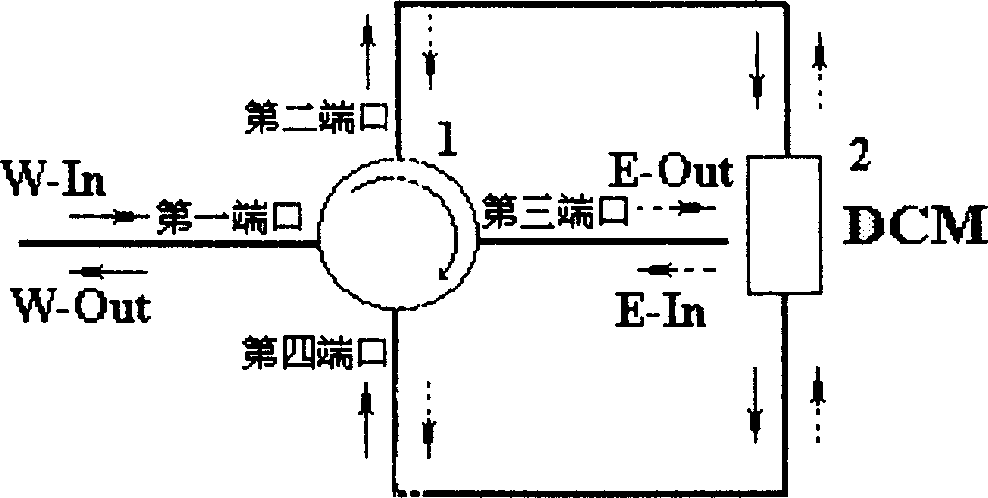
[0014] The structure of the two-way optical fiber dispersion compensation device proposed by the present invention is as follows: figure 1 As shown, it includes a dispersion compensation module 2 and a four-port first optical circulator 1, the first port of the first optical circulator 1 is connected to the first transmission channel, the third port is connected to the second transmission channel, and the second The port and the fourth port are connected through a dispersion compensation module (DCM). The first transmission channel includes both the input optical signal (W-In) and the output optical signal (W-Out); the second transmission channel also includes the input optical signal (E-In) and the output optical signal (E-Out) ), so it is a bidirectional optical fiber dispersion compensation device.

[0015] Dispersion compensation module (DCM) 2 ...


PUM


Abstract

The two-way fibre dispersion compensation equipment includes a dispersion compensation module and a first optical circulator with four ports, in which first port is connected with first transmission channel, third port is connected with second transmission channel, and second port and fourth port are connected by means of dispersion compensation module. Said invention includes an optical circulator with four ports, so that it cna utilize the irrevesible principle of optical circuit to make inputted light from different directions pass through same dispersion compensation module to make dispersion compensation so as to greatly raise utilization rate of dispersion compensation module. By adding one or several optical circulators it can utilize same dispersion compensation module to make dispersion compensation of various optical signals with different fibres and transmission directions.

Description

technical field [0001] The invention belongs to the technical field of optical dispersion compensation, and in particular relates to a dispersion compensation device that can improve the utilization rate of dispersion compensation optical fibers. Background technique [0002] With the development of dense wavelength division multiplexing (DWDM)-based optical fiber communication technology, dispersion compensating fiber (DCF), as the most mature dispersion compensation technology, has been widely used in DWDM systems. Existing dispersion compensating devices generally input an optical signal into one end of a dispersion compensating fiber, perform a compensation with the dispersion compensating fiber, output it from the other end, and then transmit it. In order to improve the optical transmission performance, it is generally achieved by increasing the dispersion coefficient of the dispersion compensation fiber, which can not only shorten the length of the dispersion compensat...

Claims


Application Information

Patent Timeline
Patent Type & Authority Applications(China)
IPC IPC(8): G02B6/24H04B10/2525H04J14/02
Inventor 李长春常志文
Owner HUAWEI TECH CO LTD
Why Eureka
Try Eureka