Sputtering method

A sputtering and sputtering gas technology, applied in sputtering plating, ion implantation plating, lighting and heating equipment, etc., can solve the problems of time waste required for exchange, inability to perform film forming operations, etc., to shorten the processing time. effect of time

Inactive Publication Date: 2003-04-30
ULVAC INC
View PDF0 Cites 2 Cited by
  • Summary
  • Abstract
  • Description
  • Claims
  • Application Information

AI Technical Summary

Problems solved by technology

When the processed substrate is replaced with a substrate not shown, since the film formation operati

Method used


Image

  • Sputtering method
  • Sputtering method
  • Sputtering method

Examples


Embodiment Construction

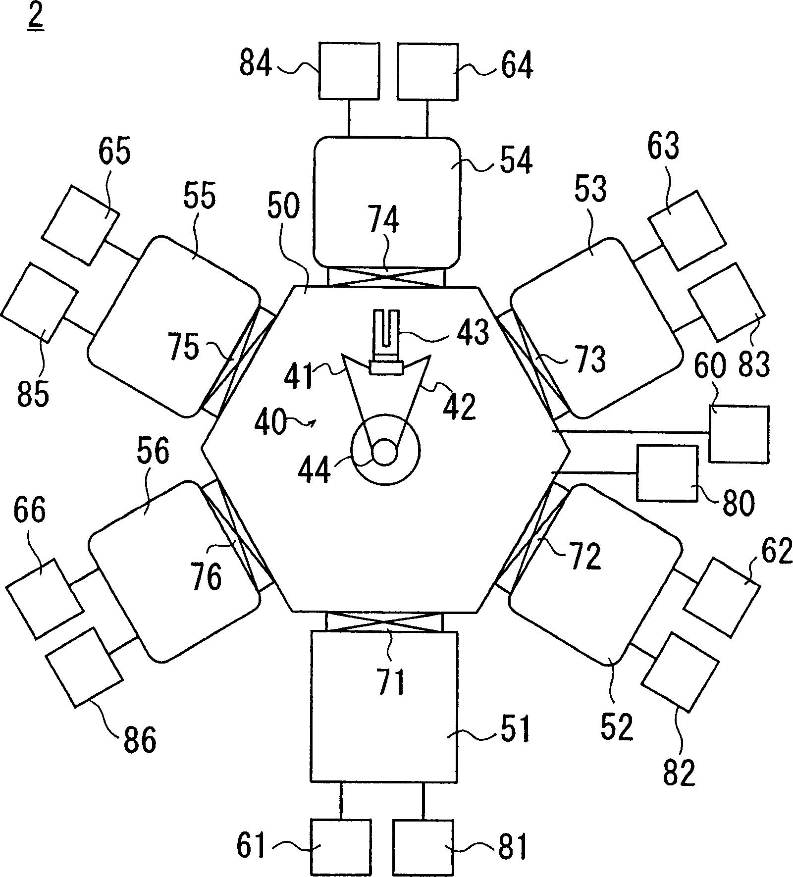
[0038] figure 1 The symbol of represents an example of the vacuum processing apparatus which can employ|adopt the sputtering method of this invention.

[0039] The vacuum processing device 2 has a transport chamber 50, an in-out chamber 51, and processing chambers 52-56. The inlet and outlet chamber 51 and each processing chamber 52-56 communicate with the side of the transfer chamber 50 through gate valves 71-76, respectively.

[0040] In the delivery chamber 50, the access chamber 51, and the processing chambers 52-56, there are respectively connected vacuum systems 60-66 and gas input systems 80-86. When closing the gate valves 71-76 and making the vacuum systems 60-66 work , the interiors of the in-out chamber 51, the transfer chamber 50, and the processing chambers 52-56 can be evacuated individually.

[0041] Gas input systems 82-86 associated with each of the processing chambers 52-56 are associated with gas cylinders corresponding to the processing performed within ...


PUM


Abstract

This invention is to provide a technique of continuously performing sputtering. During a film is formed on the surface of a substrate 5a held by a holding plate 12 by keeping the holding plate 12 inside a treatment chamber in an erected position and sputtering a target 26, an untreated substrate 5b is mounted on the hand 43 of a substrate conveying robot in a conveying chamber, the pressure in the conveying chamber is adjusted to a value substantially equal to the pressure in the treatment chamber, and the substrate 5b is conveyed into the treatment chamber and is mounted on the holding plate 12 kept in a horizontal position. The conveying time does not add any additional time because the untreated substrate can be conveyed into the treatment chamber during sputtering.

Description

technical field [0001] The invention relates to the technical field of vacuum processing, in particular to the technology of continuously vacuum processing multiple substrates. Background technique [0002] Conventionally, a multi-chamber vacuum processing apparatus in which a plurality of processing chambers are connected around one transfer chamber has been used as a mass production apparatus for forming a thin film on a substrate surface. Figure 19 The symbol 102 of represents this vacuum processing apparatus. Around the transfer chamber 150, a plurality of processing chambers are connected (here, two processing chambers 151, 153 are shown). [0003] Taking a processing chamber 153 as an example to illustrate the internal structure, the transfer port 124 is opened on the wall of the processing chamber 153 that is connected to the transfer chamber 150 . The delivery port is provided with an unshown gate valve. When the delivery port 124 is blocked by the gate valve, the ...

Claims


Application Information

Patent Timeline
IPC IPC(8): B65G49/00B65G49/07C23C14/22C23C14/34C23C14/56H01L21/677H01L21/68
CPCC23C14/34C23C14/568
Inventor 末代政辅宍仓真人大空弘树
Owner ULVAC INC
Why Eureka
Try Eureka