Laser quench controlling method and laser quencher

A technology of laser quenching and control method, applied in quenching device, laser welding equipment, heat treatment process control and other directions, can solve problems such as low irradiation energy, inability to quench action, and inability to quench

Inactive Publication Date: 2003-05-14
YAMAZAKI MAZAK KK
View PDF0 Cites 20 Cited by
  • Summary
  • Abstract
  • Description
  • Claims
  • Application Information

AI Technical Summary

Problems solved by technology

[0003] However, such temperature control is not performed in conventional laser hardening equipment.
In addition, although an infrared sensor or the like detects the quenched part from the outside and measures the temperature of the quenched part, etc., as described above, the nozzle that emits the laser beam swings the laser beam in a direction intersecting the feeding direction. Three-dimensional quenching, complex movements, so getting sensors to track is difficult and not practical
[0004] In addition, in the method of quenching the workpiece with a predetermined width by oscillating the laser beam in a direction crossing the feed direction, although the workpiece can be quenched with any width, the relative difference between the laser beams for quenching The moving speed of the workpiece becomes always variable
Therefore, if only the specified output laser beam is irradiated on the workpiece, at the position where the relative speed of the laser relative to the workpiece decreases, the irradiation energy per unit area of ​​the quenched part of the workpiece will be too high, and the workpiece will melt; When the relative speed is at the rising position, the irradiation energy per unit area is too low, and the temperature of the workpiece cannot rise to the specified quenching temperature, resulting in the inconvenience that it cannot be quenched.
Therefore, in addition to measuring the correct temperature of the above-mentioned quenching part, if the irradiation energy of the laser beam relative to the workpiece is not properly controlled to match the amplitude of the laser beam, a suitable quenching action cannot be performed.

Method used


Image

  • Laser quench controlling method and laser quencher
  • Laser quench controlling method and laser quencher
  • Laser quench controlling method and laser quencher

Examples


Embodiment Construction

[0043] Embodiments of the present invention will be described below with reference to the drawings.

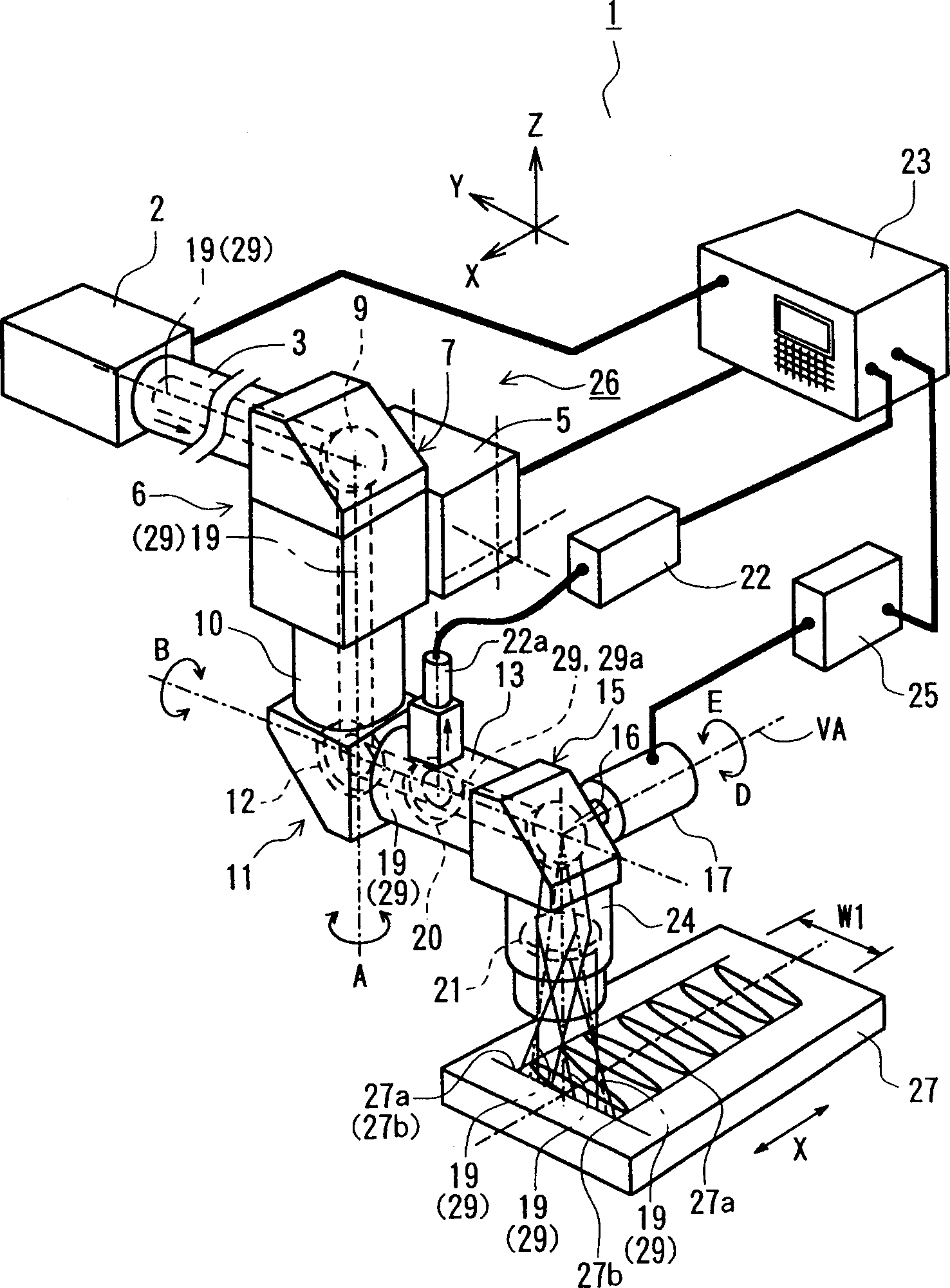
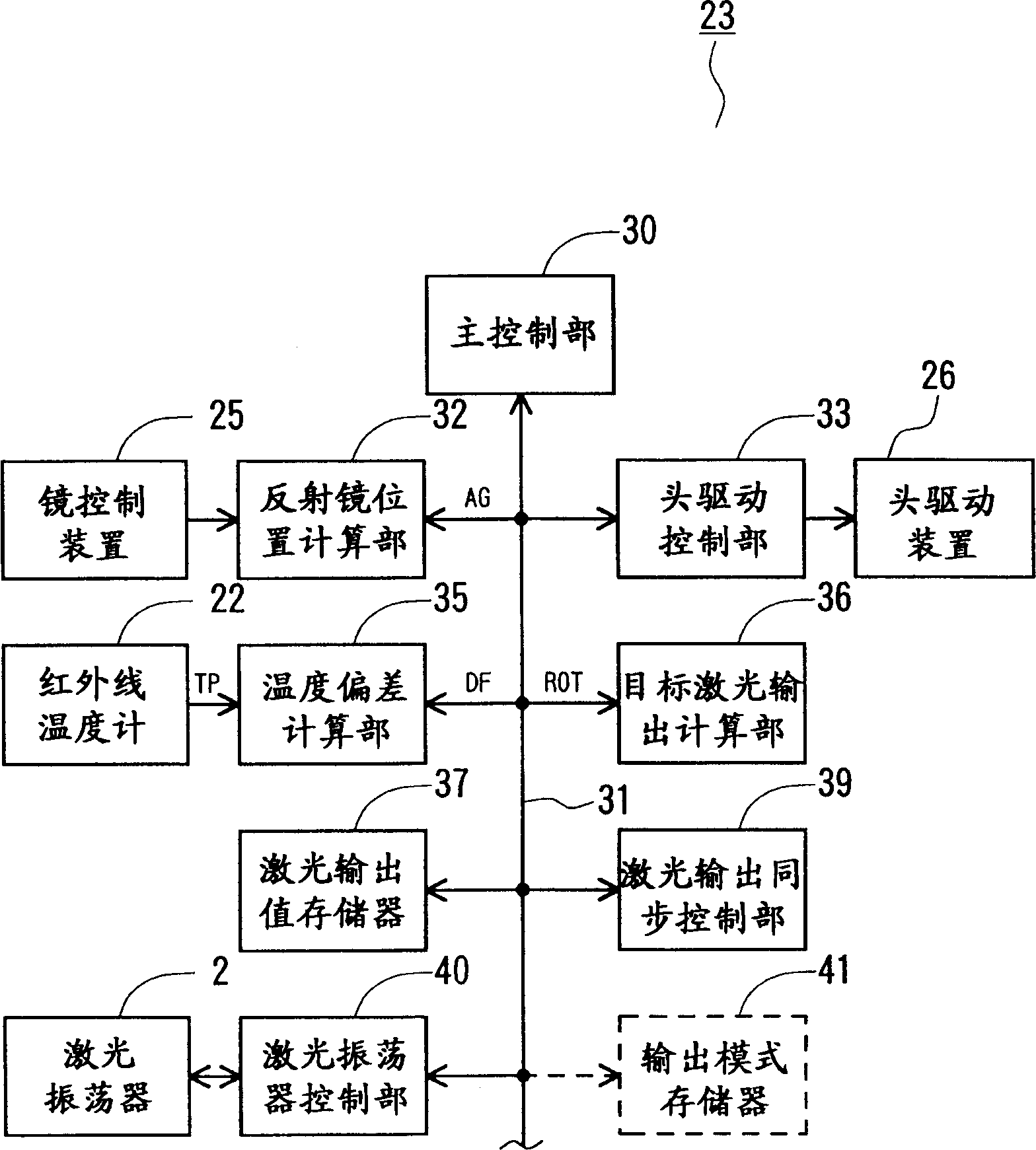
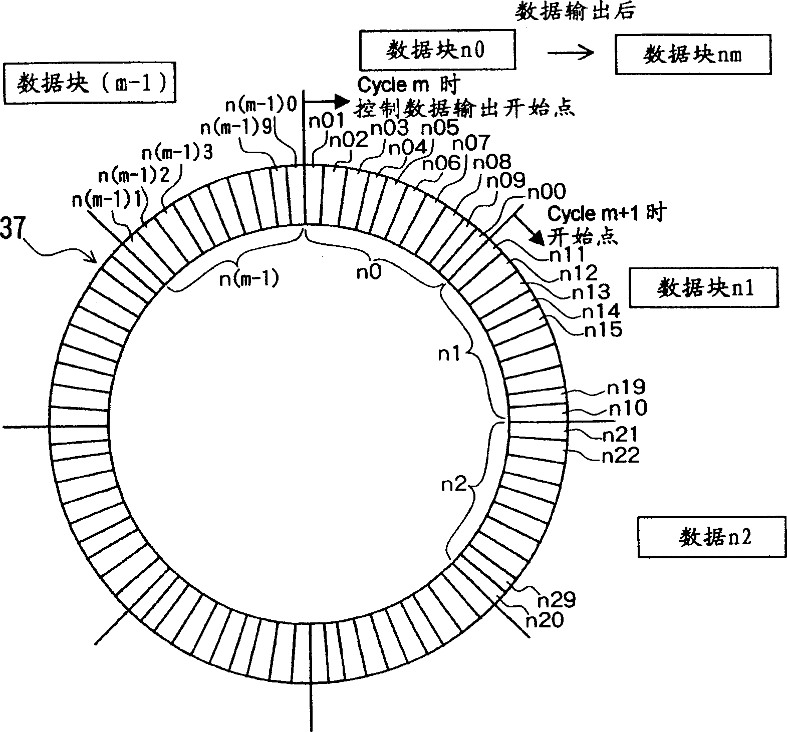
[0044] figure 1 It is a schematic perspective view showing the main part of the laser hardening device applicable to the present invention, figure 2 is a block diagram showing the main parts of the NC device, image 3 is a pattern diagram showing the contents of the laser output value memory, Figure 4 is the schematic diagram of the quenching trajectory of the laser beam, Figure 5 is a schematic diagram showing the contents of each data block in the laser output value memory, Image 6 (a) is a graph showing the trajectory of the laser beam (quenching cycle); (b) is a graph showing the velocity of the laser beam relative to the workpiece corresponding to (a); (c) is an example of a laser output pattern corresponding to (a) (d) is a graph showing another example of the laser output mode corresponding to (a).

[0045] like figure 1 As shown, the laser quenching device 1...


PUM


Abstract

In hardening with laser beam by irradiating laser beam. 29 on a workpiece 27, oscillating the laser beam so as to heat a workpiece with a hardening width W1, laser beam output in both end portions (times (1), (5), (6), (10) of FIG 4, for instance) of amplitude of the laser beam is made lower than one of a center portion (times (3), (4), (7), (8) of FIG 4, for instance) of the amplitude. Relative moving velocity of the laser beam with respect to workpiece is decreased, and the quantity of giving energy of the laser beam in both end portions of the amplitude where the density of giving energy of laser beam is high is decreased so as to equalize quantity of aiming energy in the whole hardening cycle. By doing so, a proper hardening action is possible.

Description

technical field [0001] The present invention relates to a laser quenching control method and a laser quenching device capable of accurately measuring and managing the temperature of a quenching part. Background technique [0002] Recently, although a method of quenching the workpiece with a predetermined width by oscillating the laser beam in a direction crossing the feed direction has been proposed, it is necessary to accurately detect the temperature of the quenched part when performing quenching properly, and perform Temperature management of the site. [0003] However, in the conventional laser hardening apparatus, such temperature management is not performed. In addition, although an infrared sensor or the like detects the quenched part from the outside and measures the temperature of the quenched part, etc., as described above, the nozzle that emits the laser beam swings the laser beam in a direction intersecting the feeding direction. Three-dimensional quenching, co...

Claims


Application Information

Patent Timeline
Patent Type & Authority Applications(China)
IPC IPC(8): B23K26/06B23K26/08B23K26/42C21D1/09C21D11/00
CPCB23K26/0807C21D11/00B23K26/0626B23K26/426B23K26/428B23K26/0846C21D1/09B23K26/082B23K26/705B23K26/707B23K26/352
Inventor 山崎恒彦宫川直臣井上利彦利俊彦松村勝
Owner YAMAZAKI MAZAK KK
Why Eureka
Try Eureka