Laser quenching equipment and use method

A technology of laser quenching and equipment, which is applied in the direction of quenching devices, heat treatment equipment, furnaces, etc., can solve the problems of heat softening in the quenching area, achieve the effects of saving procedures and costs, improving automation, and rapid laser surface quenching

Inactive Publication Date: 2015-07-15
LIAONING UNIVERSITY OF TECHNOLOGY
View PDF5 Cites 7 Cited by
  • Summary
  • Abstract
  • Description
  • Claims
  • Application Information

AI Technical Summary

Problems solved by technology

[0003] The purpose of this invention is to provide a laser quenching equipment, which is used to solve the heat softening problem of the quenching area caused by heat accumulation in the laser quenching process of shaft parts, to ensure that the surface hardness of shaft parts after laser quenching is basically unchanged, and to ensure that the laser Stability of workpiece quality after quenching

Method used


Image

  • Laser quenching equipment and use method
  • Laser quenching equipment and use method
  • Laser quenching equipment and use method

Examples


Embodiment Construction

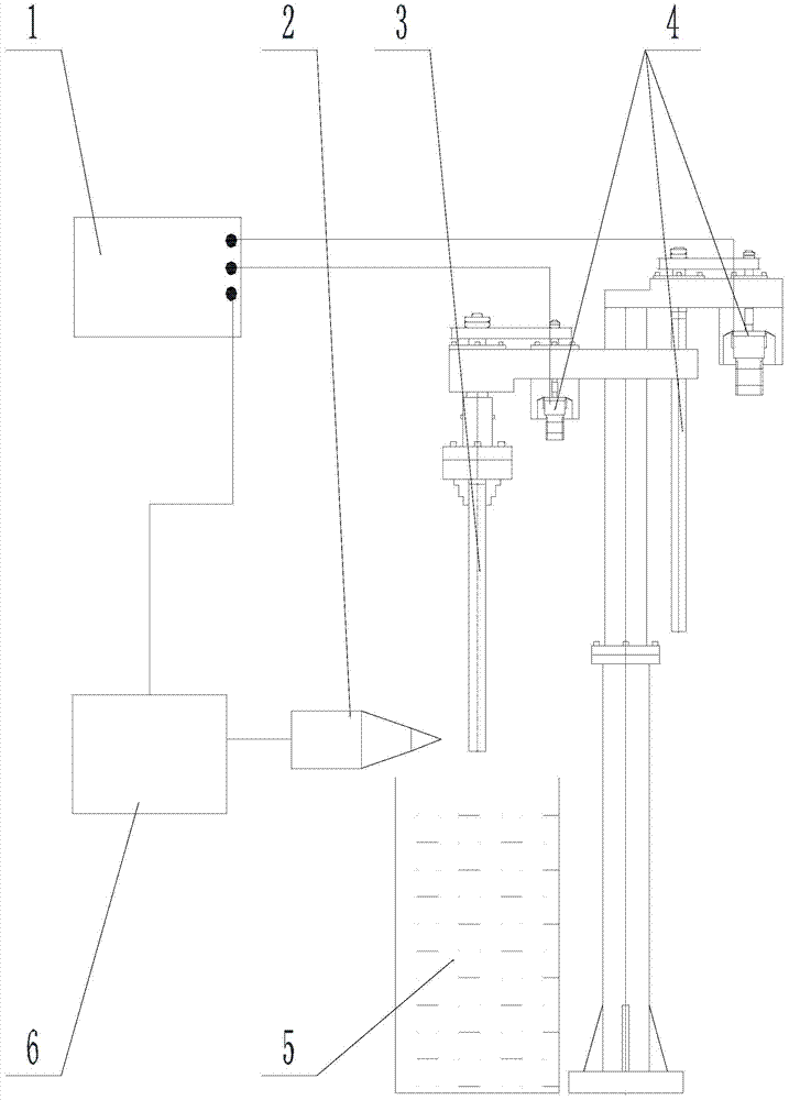
[0025] Such as figure 1 As shown, a laser hardening equipment includes a programmable controller 1, a laser 6, a laser head 2 connected to the laser 6 and used for laser hardening the workpiece 3, and used to clamp the workpiece 3 and drive the movement of the workpiece 3 The mechanism 4 is located at the cooling liquid tank below the workpiece 3, and the cooling liquid 5 is housed in the cooling liquid tank.

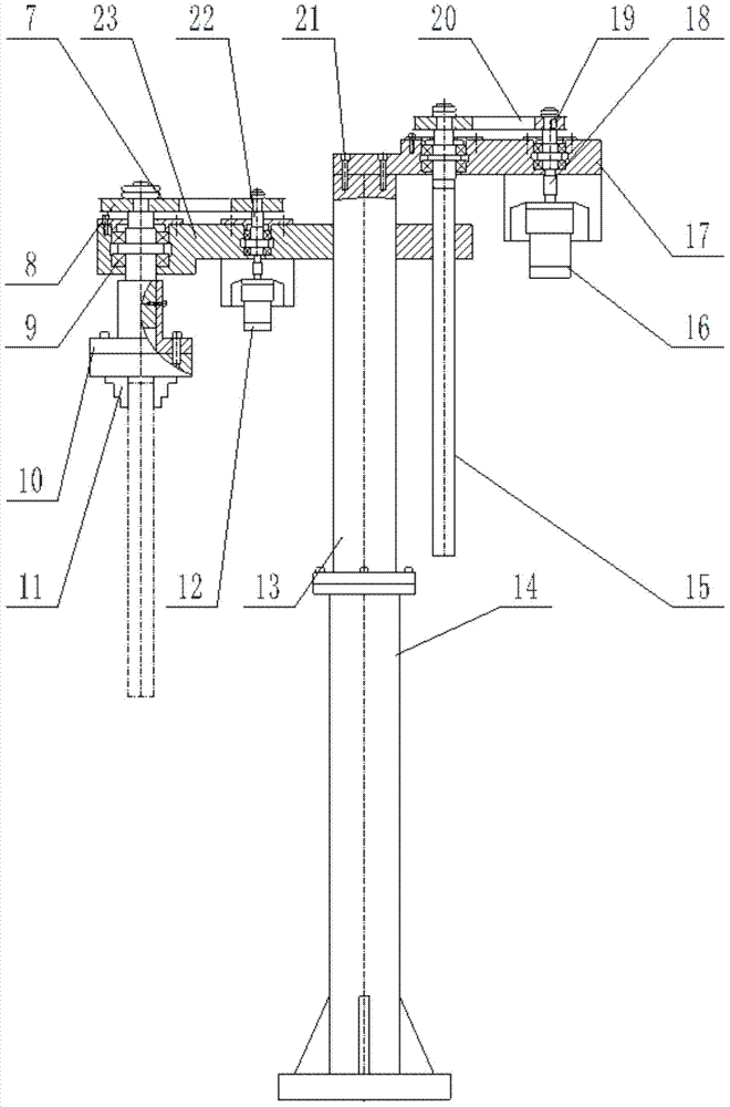
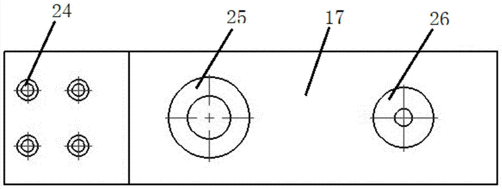
[0026] Such as figure 2 Shown motion mechanism 4 has base 14, and base 14 top is provided with guide rod 13, and the top of guide rod 13 is detachably installed fixed plate 17, and fixed plate 17 is provided with motor II 16 and leading screw 15, and fixed plate 17 is as image 3 with 4 As shown, there are installation holes I24, installation holes II25 and installation holes III26. The fixed plate 17 is fixed to the top of the guide rod 13 through the installation holes I24. There is a screw bearing in the installation hole II25, and the screw 15 is installed on the...


PUM


Abstract

The invention discloses laser quenching equipment and a use method. The equipment comprises a programmable logic controller, a laser, a laser head, a motion mechanism for driving a workpiece to move and a cooling liquid tank. The motion mechanism is provided with a base and a guide rod, a fixed plate is arranged on the guide rod, a motor II and a lead screw are arranged on the fixed plate, and the motor II drives the lead screw to rotate through a belt II. A connecting plate is arranged on the guide rod, a guide hole is formed in the connecting plate, the connecting plate is arranged on the guide rod in a sleeving mode through the guide hole, a screw hole matched with the lead screw is formed in one side of the connecting plate, a motor I and a connecting assembly are arranged on the other side of the connecting plate, the workpiece is arranged at the lower end of the connecting assembly, and the motor I acts on the connecting assembly through a belt I to drive the workpiece to rotate. The motor I, the motor II and the laser are in wire connection with the programmable logic controller. According to the equipment, the stability of the quality of the workpiece is ensured after laser quenching, the advantages of being high in automation degree and improving work efficiency are achieved, no additional processing exists almost, and procedures and cost are saved.

Description

technical field [0001] The invention relates to the field of laser surface quenching of shaft parts, in particular to a laser quenching device and a use method. Background technique [0002] At present, when shaft parts are subjected to laser quenching, the hardness is often sharply reduced due to temper softening caused by multiple laps. In addition, there is a problem that the production efficiency is too low when the temperature of the part is lowered after single-pass laser quenching before starting the next pass of laser quenching. Therefore, there is an urgent need to develop laser quenching equipment that can achieve high hardness and high efficiency on the surface of the workpiece. Contents of the invention [0003] The purpose of this invention is to provide a laser quenching equipment, which is used to solve the heat softening problem of the quenching area caused by heat accumulation in the laser quenching process of shaft parts, to ensure that the surface hardn...

Claims


Application Information

Patent Timeline
Patent Type & Authority Applications(China)
IPC IPC(8): C21D1/09C21D1/62C21D9/28C21D9/30
Inventor 何力佳王建中张子煜赵晓杰
Owner LIAONING UNIVERSITY OF TECHNOLOGY
Why Eureka
Try Eureka