
Thin-wall gear ring type part quenching method for keeping accuracy level

A thin-walled ring gear, high-precision technology, used in furnace types, furnaces, heat treatment equipment, etc., can solve problems such as scorching and overheating, quenching cracks, environmental pollution, etc., to improve production efficiency, reduce deformation, and achieve accurate positioning. Effect

Inactive Publication Date: 2012-12-05
JIANGLU MACHINERY & ELECTRONICS GROUP
View PDF8 Cites 7 Cited by
  • Summary
  • Abstract
  • Description
  • Claims
  • Application Information

AI Technical Summary

Problems solved by technology

[0002] In traditional heat treatment production, due to the complex structure and large cross-section changes of thin-walled ring gear parts, if the overall quenching method is adopted, due to the superposition of thermal stress and tissue stress, it is easy to cause deformation and distortion of the parts or form quenching cracks; induction quenching due to induction Parameters such as magnetic field and current are difficult to control, prone to scorching and overheating, and form soft bands, resulting in deep hardened layers and uneven hardness of parts; in order to ensure local wear resistance and improve surface hardness, chemical heat treatment carburizing or nitrogen In this way, the non-seepage surface of the parts must be partially impermeable through measures such as copper plating, which is easy to cause pollution to the environment. In addition, in order to effectively control the heat treatment deformation, the method of repeated alignment and increasing the machining allowance is adopted in the process. , seriously restricting the improvement of production progress and product performance

Method used


Image

  • Thin-wall gear ring type part quenching method for keeping accuracy level
  • Thin-wall gear ring type part quenching method for keeping accuracy level
  • Thin-wall gear ring type part quenching method for keeping accuracy level

Examples


Embodiment Construction

[0017] The steps of the present invention are as follows:

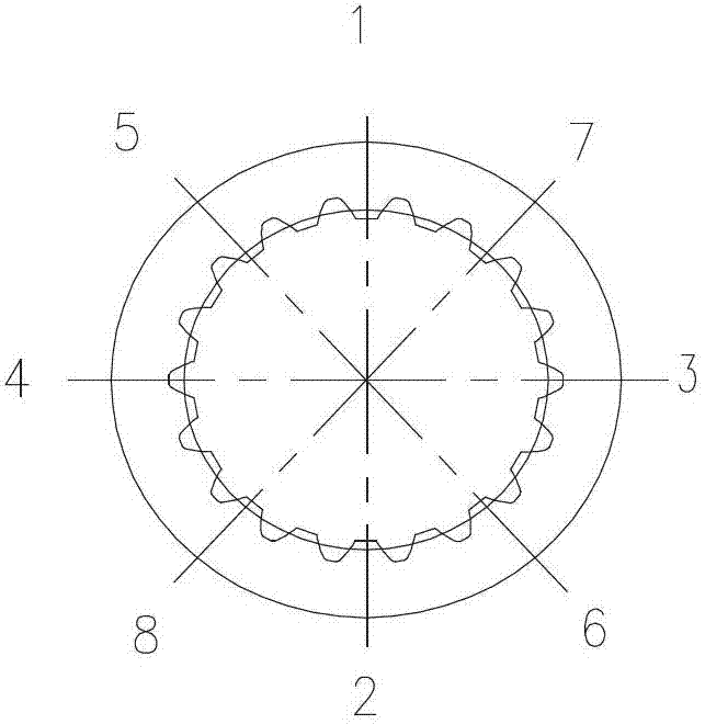
[0018] Step 1. The thin-walled ring gear parts of medium carbon nitriding steel are processed according to the cutting amount specified in the process, and the stress relief and tempering are carried out respectively. The main purpose is to eliminate the mechanical stress of the parts as much as possible. After the processing is completed, it is cleaned and dried, and its processing accuracy is 7 grades.

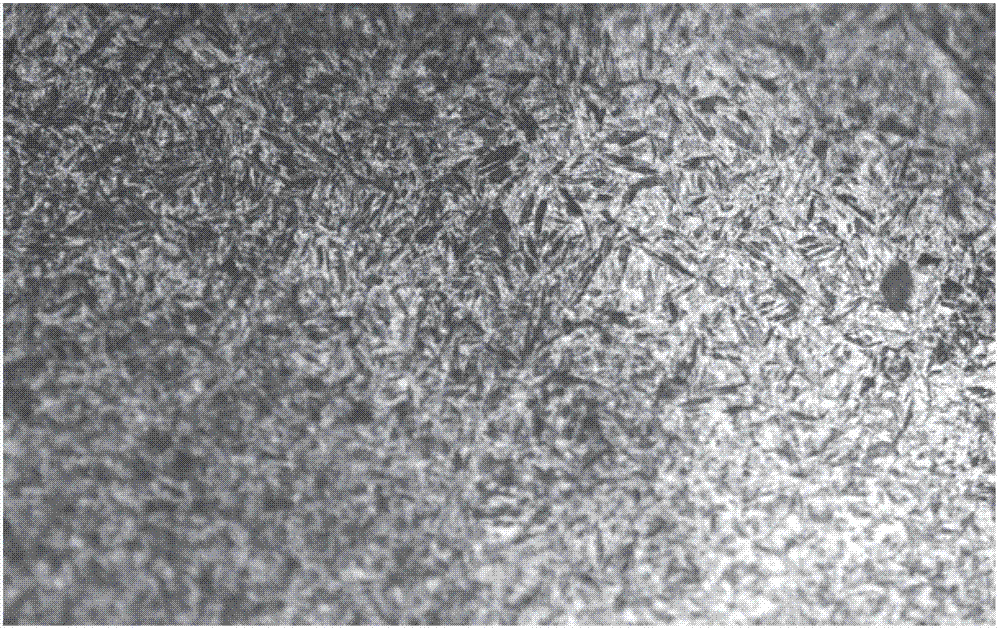
[0019] Step 2. Use a special coating material to evenly coat the surface to be strengthened, scan the surface of the workpiece with a high-energy laser beam, the surface material of the workpiece absorbs the laser radiation energy and converts it into heat energy, and the heat conduction makes the temperature around the material rise at an extremely fast speed To the process temperature above the austenite transformation, and then through the self-cooling effect of the material matrix, the heated surface material is...


PUM


Abstract

The invention relates to a thin-wall gear ring type part quenching method for keeping the accuracy level. The method comprises the following steps of: performing coarse and fine machining on a thin-wall gear ring type part of steel for nitriding medium carbon according to a process specified cutting amount in a machining process; destressing and tempering respectively; uniformly coating a surface to be reinforced with a coating material; scanning the surface of a workpiece by using high energy laser beams to obtain a uniform-surface martensite structure; sequentially and gradually heating the surface to be hardened of the part by adopting a symmetric equant gradient heating way; and comparing two thermal treatment processes including a tool positioning and laser quenching process and a nitriding process to obtain a martensite structure with surface compression stress through laser quenching, so that the fatigue resistance of the surface of the part is improved remarkably. The method meets the requirement of product performance; and meanwhile, the symmetric equant gradient heating way is adopted, so that part deformation is reduced, part machining procedures can be reduced on the basis of not lowering the machining accuracy level, and the requirement of product performance is met.

Description

technical field [0001] The invention relates to a method for quenching parts of thin-walled ring gears that maintains precision grades. This method can be widely used in surface strengthening of thin-walled ring gear parts of ordinary medium-carbon structural steel or alloy structural steel, and can replace the overall low-temperature quenching and nitriding of low-carbon steel after carburizing without reducing the machining accuracy level of the parts. . Background technique [0002] In traditional heat treatment production, due to the complex structure and large cross-section changes of thin-walled ring gear parts, if the overall quenching method is adopted, due to the superposition of thermal stress and tissue stress, it is easy to cause deformation and distortion of the parts or form quenching cracks; induction quenching due to induction Parameters such as magnetic field and current are difficult to control, prone to scorching and overheating, and form soft bands, resu...

Claims


Application Information

Patent Timeline
IPC IPC(8): C21D9/32C21D1/09
Inventor 蒋秋娥蒋亦舟谭永耀莫竞芳赵飞杨旭驰向导王倩黄玉堃
Owner JIANGLU MACHINERY & ELECTRONICS GROUP
Learn More