Light waveguide and optical fiber coupling method and device for lithium niobate modulator

A technology of fiber coupling and realization method, which is applied in the coupling, optics, instruments and other directions of optical waveguides, and can solve the problems of high manufacturing difficulty, insufficient temperature stability and mechanical properties, and high precision requirements of silicon V-groove

Inactive Publication Date: 2003-05-14
HUAWEI TECH CO LTD
View PDF0 Cites 11 Cited by
  • Summary
  • Abstract
  • Description
  • Claims
  • Application Information

AI Technical Summary

Problems solved by technology

[0018] The disadvantages of the silicon V-groove flip-chip technology are: 1. The silicon V-groove requires high precision and is difficult to manufacture; 2. The thermal expansion coefficients of silicon, quartz, and LN are different, and the glue used for bonding will be produced when the temperature changes. In severe cases, the bonding layer will be damaged; at the same time, there will be rel

Method used


Image

  • Light waveguide and optical fiber coupling method and device for lithium niobate modulator
  • Light waveguide and optical fiber coupling method and device for lithium niobate modulator
  • Light waveguide and optical fiber coupling method and device for lithium niobate modulator

Examples


Embodiment 1

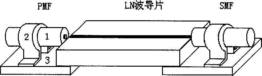
[0070] Such as Figure 6 ~ Figure 7 As shown, the coupling device described in this embodiment includes:

[0071] Two optical fibers suitable for coupling;

[0072] The fixing block for fixing the optical fiber. In this embodiment, the fixing block is a quartz capillary tube, which is sleeved outside the optical fiber and connected with the optical fiber to increase the bonding area, fix the optical fiber and protect the optical fiber;

[0073] A reinforcement block for reinforcing the optical fiber; in this embodiment, the reinforcement block is a glass capillary, which is sleeved outside the optical fiber and connected with the optical fiber to protect the optical fiber;

[0074] The gasket combination formed by several gaskets plays the role of supporting and protecting the optical fiber and the LN waveguide chip;

[0075] LN waveguide chip;

[0076] The tube shell is used to accommodate the LN waveguide chip, optical fiber, fixing block, reinforcing block and gasket com...

Embodiment 2

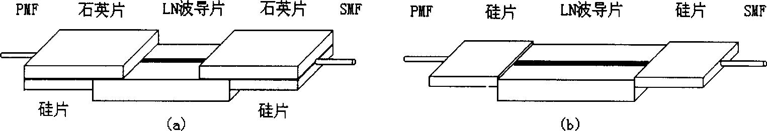
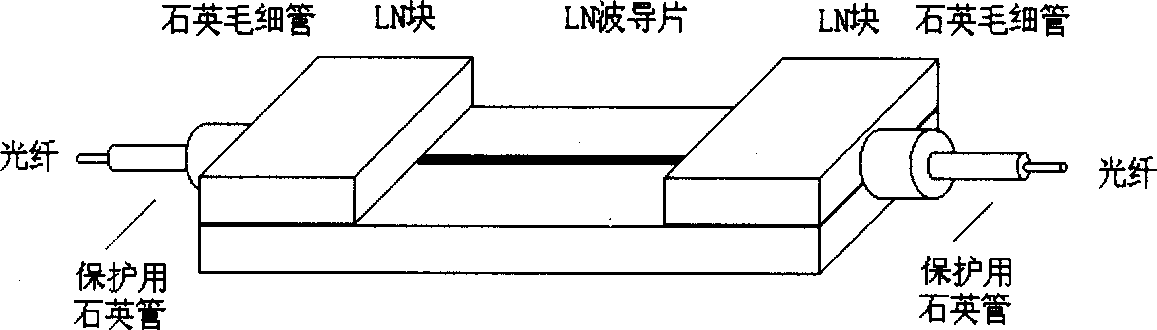
[0107] Such as Figure 7-Figure 8 As shown, the difference between this embodiment and the coupling device described in Embodiment 1 is that it mainly focuses on improving the thermal stability, mechanical properties and long-term stability of the device, so as to meet the practical requirements of the device. The difference between this embodiment and embodiment 1 is:

[0108] First, when designing the coupling fiber, replace the quartz capillary with the LN block to ensure that the LN waveguide surface and the fiber end face can still maintain the original state when the temperature changes.

[0109] Second, add an arched structure to the coupling fiber, such as Figure 8 As shown, the optical fiber is slightly bent into an arc, so that the optical fiber can eliminate the influence of temperature changes through its own deformation. The quartz capillary is selected as the new optical fiber protective layer, and the relative displacement between the optical fiber and the pr...


PUM


Abstract

The coupling device of the present invention includes two pieces of proper fiber, fiber fixing block and fiber reinforcing block; spacer combination; LN waveguide chip; and package shell. The fiber with fiber fixing block and fiber reinforcing block is supported inside the package shell and has one end connected to side of the LN waveguide chip supported by spacer combination inside the shell andthe other end extending beyond the shell and as the input or output interface, with the joint to the shell being adhered. By means of improved coupling technology and structure, the light waveguide in the modulator is coupled with fiber precisely and reliably with high stability, low additional loss, low lkight reflection, and insertion loss not affected by temperature change and mechanical vibration.

Description

technical field [0001] The invention relates to a method and a coupling device for realizing the coupling of an optical waveguide and an optical fiber for a lithium niobate modulator, belonging to the improvement of communication optical devices. Background technique [0002] With the rapid development of the information industry, communication optical devices have also made great progress in recent years, with various types and different principles. In order to meet the needs of optical fiber communication, most communication optical devices use optical fiber as the input and output interface. Similar to microelectronic chips, optical fibers or fiber arrays are used in optical devices to input optical signals into optical chips, and then output processed optical signals from them. Therefore, how to achieve precise coupling between optical fiber or optical fiber array and optical chip, obtain insertion loss independent of temperature change and mechanical vibration, and mai...

Claims


Application Information

Patent Timeline
IPC IPC(8): G02B6/26G02F1/03
Inventor 李汉国蒲天春蔡义智谭松曹宏斌
Owner HUAWEI TECH CO LTD
Why Eureka
Try Eureka