
Correction method and device of intelligent antenna subsystem

A technology of smart antennas and calibration methods, applied to antennas, transmission systems, antenna arrays, etc., can solve problems such as real-time online calibration of difficult smart antenna base stations

Inactive Publication Date: 2003-05-14
ZTE CORP
View PDF2 Cites 29 Cited by
  • Summary
  • Abstract
  • Description
  • Claims
  • Application Information

AI Technical Summary

Problems solved by technology

But for FDD-WCDMA (Frequency Division Duplex) system, the above correction method is difficult to realize real-time online correction of smart antenna base station

Method used


Image

  • Correction method and device of intelligent antenna subsystem
  • Correction method and device of intelligent antenna subsystem
  • Correction method and device of intelligent antenna subsystem

Examples


Embodiment Construction

[0046] The following is based on Figure 1 to Figure 7 Examples of the present invention are given to further illustrate the method and device of the present invention.

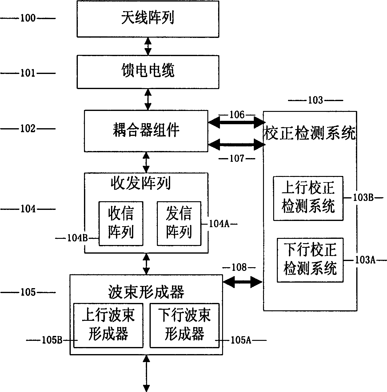
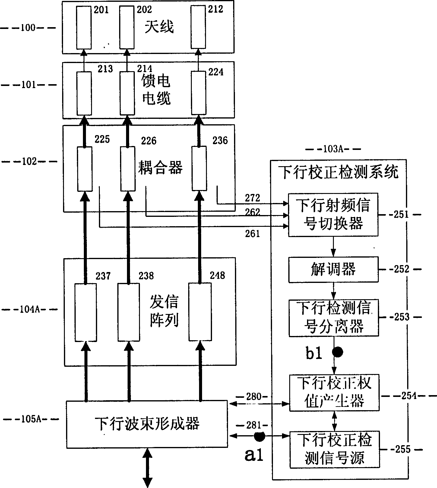
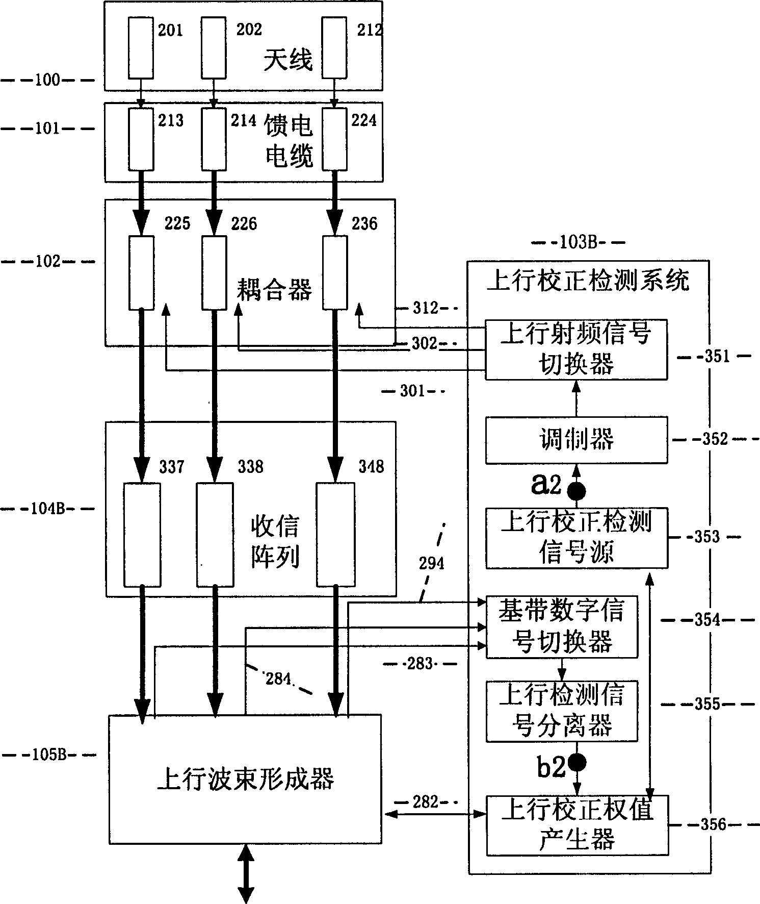
[0047] See figure 1 , the figure shows the structure of the FDD-WCDMA system smart antenna base station using the method and device of the present invention. It mainly includes an antenna array 100, a feeder cable 101, a coupler assembly 102, a transceiver array 104, a beamformer 105, and an uplink and downlink correction radio frequency signal coupling cable 106, 107 and the coupler assembly 102, which are sequentially connected in a two-way circuit. A correction detection system 103 connected in two directions, and a digital communication interface 108 connecting the correction detection system 103 and the beamformer 105 . The above-mentioned transceiver array 104 is composed of 12 transceiver channels, and the interface signals with the beamformer 105 are digital signals; the said digital communication i...


PUM


Abstract

The intelligent antenna subsystem correcting method and device is used in frequency division duplex and wideband CDMA system and the device consists of intelligent antenna and correcting detection system linked together. The correcting method includes correcting and detecting the antenna units in the antenina array and the cables in feeding cable in advance; testing the transmission parameters ofthe coupling structure comprising the coupler assembly and the correcting detection system and storing the test results in the correcting detection system; correcting the transmission parameters of the upward and downward transceiving channels of the detecting system when the system is in normal operation state and calculating the correcting weight value output to the base band beam shaper for weighting.

Description

technical field [0001] The present invention relates to a calibration method and device for a smart antenna radio frequency subsystem in a wideband code division multiple access system, in particular to a frequency division duplex-wideband code division multiple access (FDD-WCDMA) system smart antenna base station array radio frequency A method and device for correcting channel amplitude and phase errors. Background technique [0002] The essence of smart antenna is the core of array antenna technology and advanced signal processing method. The basic idea of ​​a smart antenna is to use an antenna array composed of multiple antenna units (the coherence between the units satisfying the coherence characteristic) in the base station. By weighting the phase and amplitude of the signals received and transmitted by multiple antenna units, the antenna beam can be controlled. Direction and shape, and can form multiple independent beams to achieve directional transmission and recepti...

Claims


Application Information

Patent Timeline
Patent Type & Authority Applications(China)
IPC IPC(8): H04B17/00H01Q21/00H04B17/12H04B17/21
Inventor 李景毅王允宽
Owner ZTE CORP
Learn More