Dipole logging tool

A technology of logging instruments and dipoles, which is applied in the seismology and other directions for logging records, and can solve the problems of limited horizontal distance of the radiation surface and imperfect dipoles.

Inactive Publication Date: 2003-05-14
SCHLUMBERGER OVERSEAS SA
View PDF9 Cites 9 Cited by
  • Summary
  • Abstract
  • Description
  • Claims
  • Application Information

AI Technical Summary

Problems solved by technology

Each emitter of these types is an imperfect dipole, since the azimuthal extent of the effective emitting surface (i.e. the apertures in the body of the instrument) is limited

Method used


Image

  • Dipole logging tool
  • Dipole logging tool
  • Dipole logging tool

Examples


Embodiment Construction

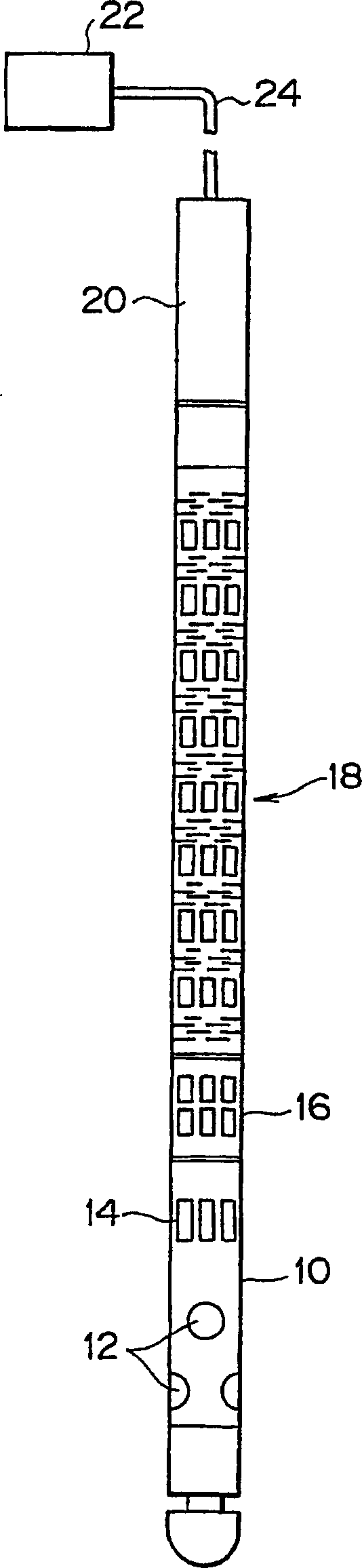
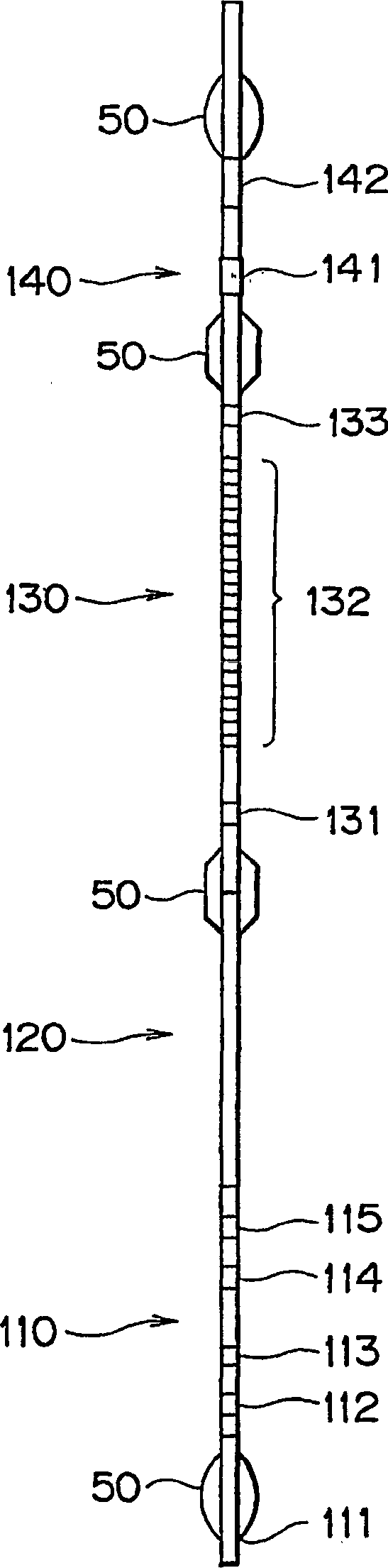
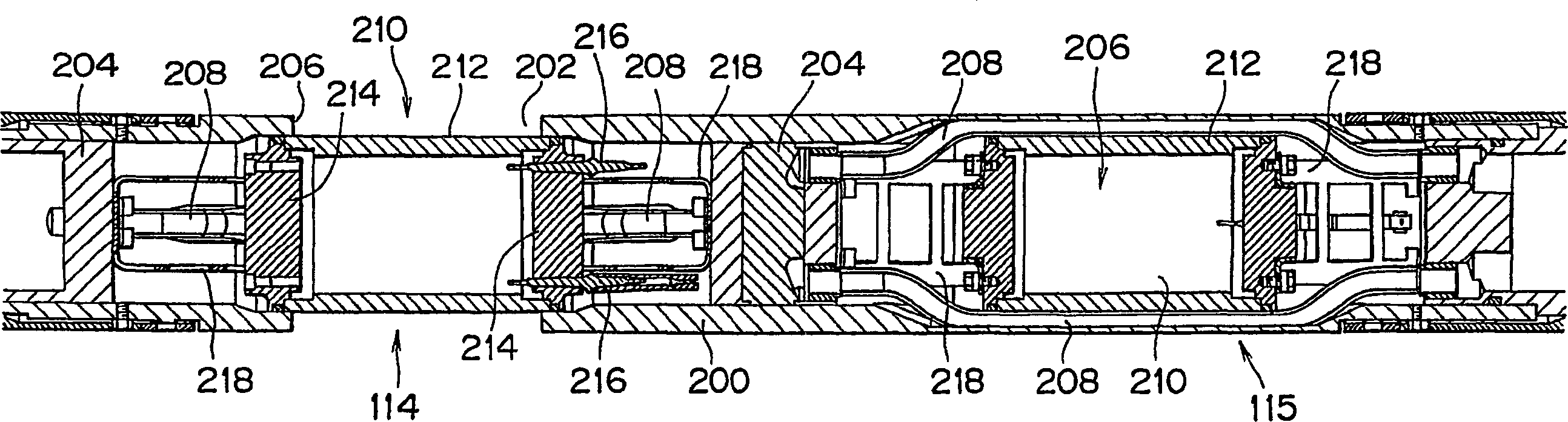
[0041] figure 2 A logging tool according to an embodiment of the present invention is shown incorporating a novel dipole emitter. The illustrated instrument includes a transmitter section 110 having power electronics 111, a pressure compensator 112, a far monopole transmitter 113, a first dipole transmitter 114 oriented in the x-azimuth direction, and an orientation A second dipole emitter 115 in the y-azimuth direction. Monopole emitter 113 is substantially as described in US Patent 5,043,952 (herein incorporated by reference). The two dipole transmitters 114, 115 are specific implementations of the electromagnetic transducer described in US Patent 5,266,845 (herein incorporated by reference), which will be addressed below Figure 4 be described in more detail. The spacing section is designed to provide adequate separation of the transmitting section 110 from the receiving section 130 while avoiding interference of signals detected in the receiving section 130 by acoustic...


PUM


Abstract

A logging tool having a tool body, which can be positioned in a fluid-filled borehole, including a receiver section and a dipole transmitter; wherein the dipole transmitter includes a transducer with a shell having a reaction mass and a motor located therein, the motor operatively connecting the shell and the reaction mass such that only an outer surface of the shell is in contact with the fluid in the borehole. This new type of dipole source for well logging involves shaking all or part (axially) of a dipole tool body to produce a pure, broadband acoustic dipole signal while at the same time coupling as little energy as possible into the tool body. Important variations on this idea include a linear phased array of shaker sources, and active cancellation of tool borne noise.

Description

technical field [0001] The present invention relates to acoustic borehole logging tools having dipole emitters. In particular, the present invention relates to the use of a novel dipole transmitter in a borehole logging tool that addresses some of the shortcomings of prior art designs. Background technique [0002] The field of borehole acoustic logging in the oil and gas industry involves making acoustic measurements in boreholes at frequencies typically in the range of 500 Hz-20 kHz. Below this range is generally considered the seismic domain, and above it the ultrasonic domain. In some cases, but not in all cases, technologies and processes can be transferred between these domains. A review of the many general techniques involved in borehole acoustic logging can be found in GEO-PHYSICAL PROSPECTING USING SONICS ANDULTRASONICS, GEO-PHYSICAL PROSPECTING USING SONICS ANDULTRASONICS, Wiley Encyclopaedia of Electrical and Electronic Engineering 1999), pp. 340-365. [0003]...

Claims


Application Information

Patent Timeline
Patent Type & Authority Applications(China)
IPC IPC(8): G01V1/52
CPCG01V1/52
Inventor 戴维·霍伊尔田代齐贝努特·弗罗利赫阿兰·布里堀宏杉山均杰尔·帕邦弗兰克·莫里斯
Owner SCHLUMBERGER OVERSEAS SA
Why Eureka
Try Eureka