Fluid bearing

A technology of fluid bearings and bearing components, applied in the directions of bearings, shafts and bearings, mechanical equipment, etc., can solve the problems of bearing rigidity decline, bearing distortion, adverse effects of NRRO, etc., and achieve the effect of stable transportation and handling

Inactive Publication Date: 2003-05-21
NTN CORP
View PDF0 Cites 15 Cited by
  • Summary
  • Abstract
  • Description
  • Claims
  • Application Information

AI Technical Summary

Problems solved by technology

At this time, in the wide part of the radial bearing gap, the shelling effect of the bearing decreases due to the hydrodynamic pressure.
Therefore, it is possible that the bearing rigidity decreases in the direction of the major axis of the ellipse, causing the bearing to be twisted
Adverse effects on NRRO etc.

Method used


Image

  • Fluid bearing
  • Fluid bearing
  • Fluid bearing

Examples


Embodiment Construction

[0111] Embodiments of the present invention will be described below.

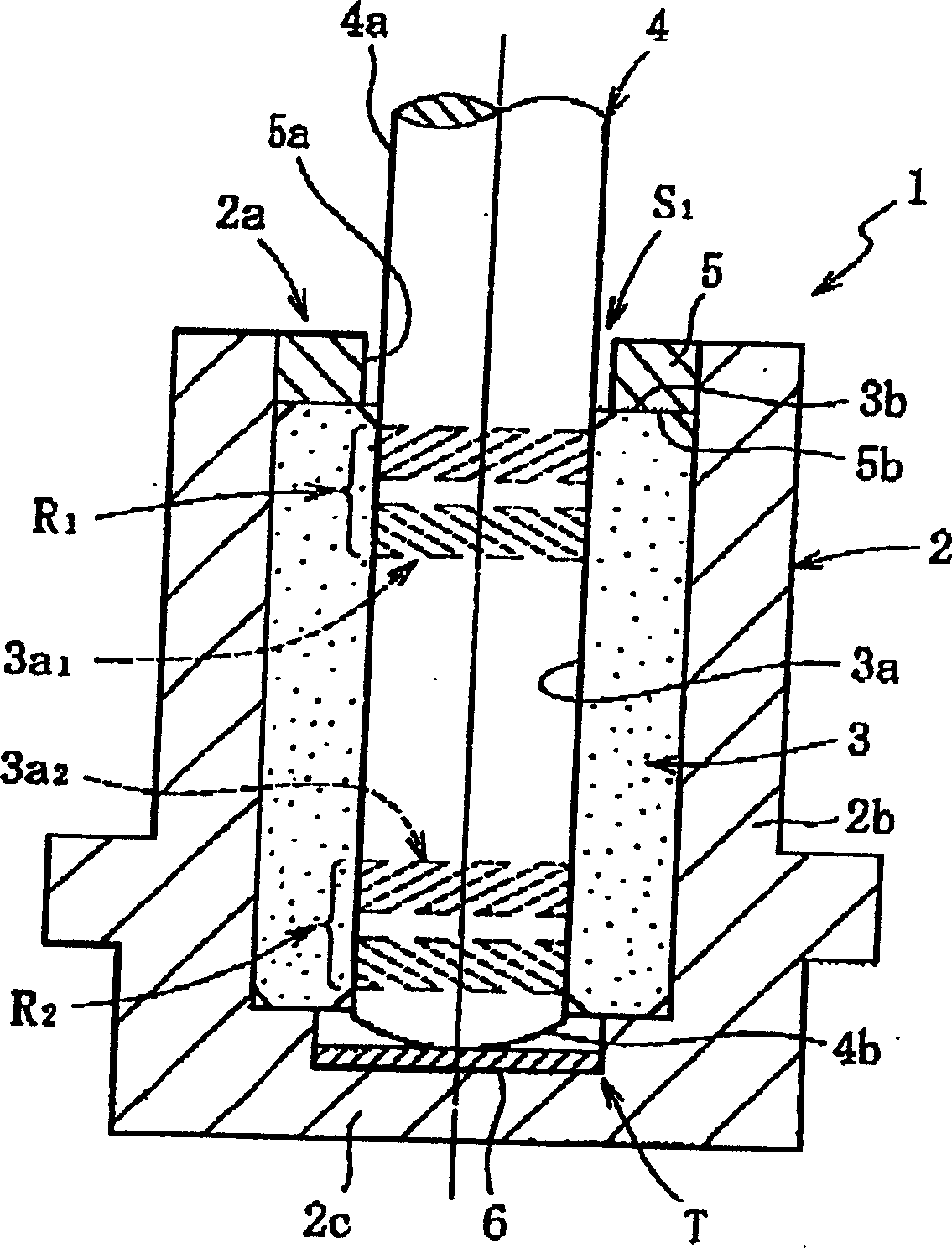
[0112] Fig. 1 shows a fluid dynamic pressure bearing device 1 according to an embodiment of the present invention. This fluid bearing device 1, for example: as shown in FIG.

[0113] Bushing 2: has an opening 2a on one end side (upper side in FIG. 1 ), has a bottom 2c on the other end side (lower side in FIG. 1 ), and has a bottomed cylindrical shape;

[0114] Bearing part 3: it is fixed on the inner peripheral surface of the shaft sleeve 2 and is cylindrical;

[0115] Shaft part 4:

[0116] Sealing member 6 : fixed to the opening 2 a of the boss 2 . As described below, between the inner peripheral surface 3a of the bearing member 3 and the outer peripheral surface 4a of the shaft member 4, the first radial bearing portion R1 and the second dynamic pressure bearing portion R2 are separated in the axial direction. In addition, a thrust bearing portion T is provided between the bottom portion 2c of the bo...


PUM


Abstract

The present invention provides a fluid bearing device. An inner space of a housing (2) sealed with a seal member (5) as well as internal pores of a bearing member (3) (pores in a porous structure) are filled with a lubricating oil without the presence of air, so that the oil surface of the lubricating oil is within a seal space S1. Under a reduced pressure of 100 Torr, no lubricating oil leaks outside of the housing (2) even at any attitude of the fluid lubricated bearing device (1) such as normal, inverted, or horizontal attitude.

Description

technical field [0001] The present invention relates to a fluid bearing device that supports a rotating part in a non-contact manner through an oil film generated in a radial bearing gap; the fluid bearing device is most suitable for use as information equipment such as disk devices such as HDD and FDD , CD-ROM, CD-R / RW, DVD-ROM / RAM and other optical disk devices, MD, MO and other optical-disk devices and other spindle motors, copiers, laser beam printers (LBP), barcode scanners and other scanning equipment motors, Or electrical equipment, such as small motors such as axial fans. Background technique [0002] The various motors mentioned above require high speed, low cost, and low noise in addition to high rotational accuracy. Among the major constituent factors in determining these performance requirements are the bearings that support the motor shaft. In recent years, the use of fluid bearings having excellent performance requirements as described above is being studied,...

Claims


Application Information

Patent Timeline
Patent Type & Authority Applications(China)
IPC IPC(8): F16C32/06
Inventor 栗村哲弥山本康裕川濑达夫
Owner NTN CORP
Why Eureka
Try Eureka