Automatic dedusting, heating, moistening and air exchanging machine

An automatic dust removal and ventilator technology, applied in heating methods, lighting and heating equipment, household heating, etc., can solve the problems of high production cost and complicated process, and achieve the effect of reduced efficacy and increased volume

Inactive Publication Date: 2003-06-04
武雄
View PDF2 Cites 9 Cited by
  • Summary
  • Abstract
  • Description
  • Claims
  • Application Information

AI Technical Summary

Problems solved by technology

Traditional exhaust fans use manual switches, but from a physiological and scientific point of view, room ventilation should be repeated at any time or in small cycles. The China Intellectual Property Office has many records on air dust removal and humidification, such as; "98232699.8 Indoor timing Dust removal fan", but there are some shortcomings, or can not meet the above requirements, or the production cost is too high, the process is too complicated

Method used


Image

  • Automatic dedusting, heating, moistening and air exchanging machine
  • Automatic dedusting, heating, moistening and air exchanging machine
  • Automatic dedusting, heating, moistening and air exchanging machine

Examples


Embodiment 1

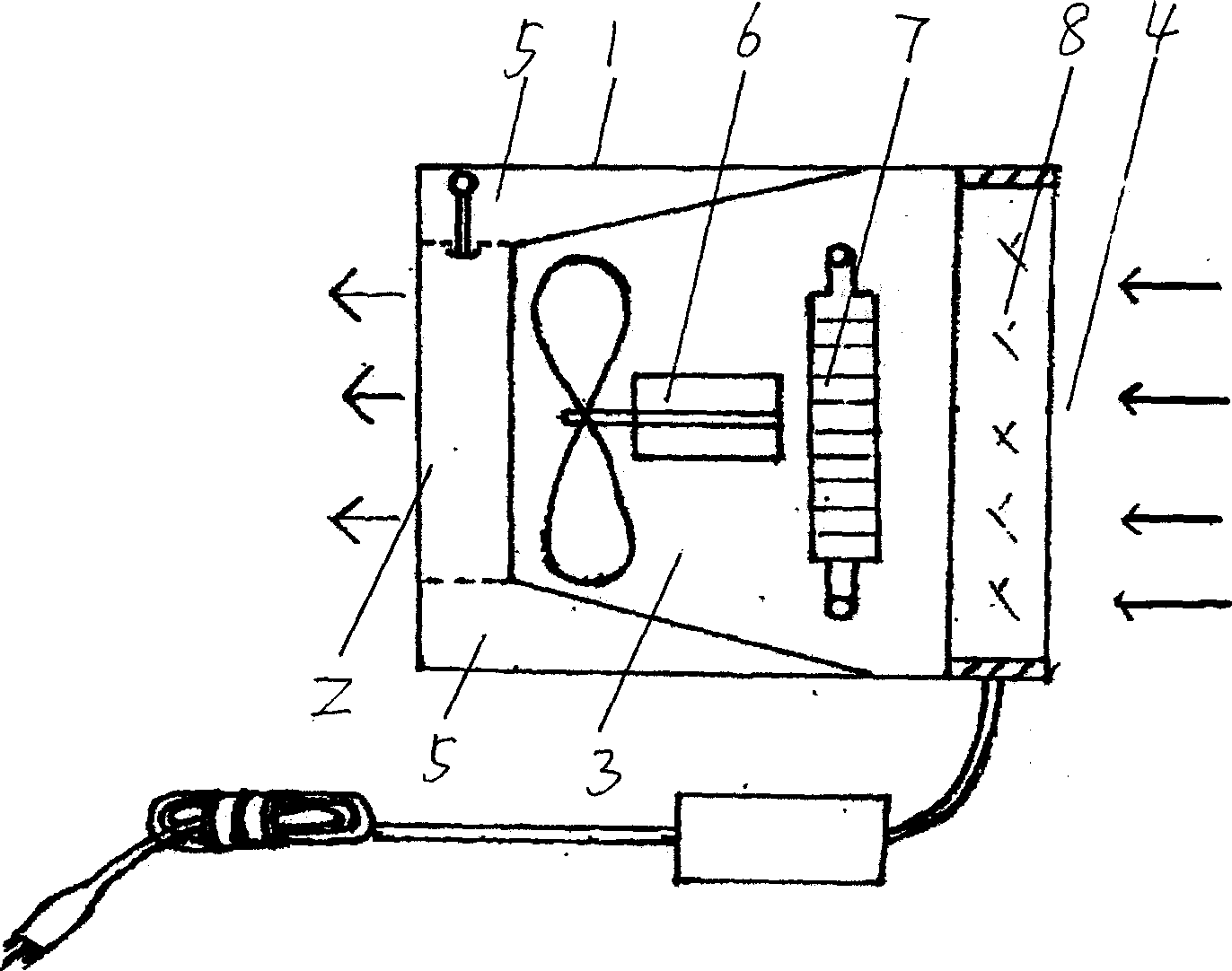
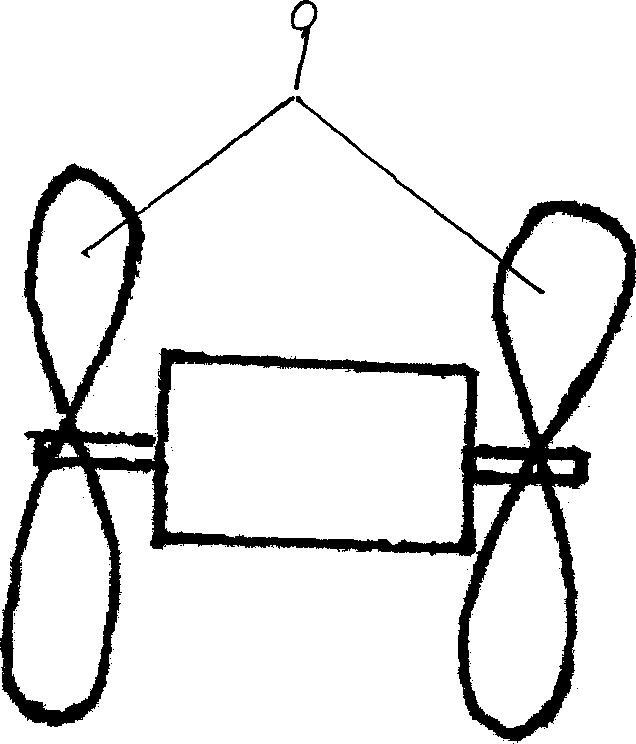
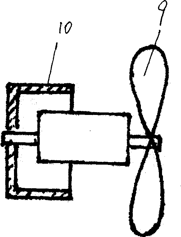
[0023] Embodiment 1. (as figure 1 , Figure 2a , image 3 , Figure 4 ) by injection molding to make the housing 1 and the water tank 11 including the air outlet 2, the air duct 3, and the air inlet 4. The air outlet 2 is a bell mouth shape with a large inside and a small outside. The water tank 11 of tuyere 2. Electric fan 6 is fixed in the air duct 3, adopts biaxial flow type fan blade 9, is respectively fixed on the front and rear ends of electric fan 6 shafts, and by air flow direction, the first fan blade is greater than the size of the second fan blade. Fix electric heat pipe 13 in air duct 3 as heating device 7, electric heat pipe 13 can adopt the warped plate electric heat pipe as 92224711.0 patent design, can add anti-radiation plate between the motor of electric fan 6 and electric heat pipe 13 if necessary. A filter 14 is installed at the air inlet 4 at the tail end of the air duct 3. The manufacturing method of the filter 14 is: take some industrial filter paper...

Embodiment 2

[0024] Embodiment 2. (as Figure 2b ,Figure 5, Figure 5a , Figure 5b) is manufactured by injection molding into a housing 1 and a water tank 11 including an air outlet 2, an air duct 3, and an air inlet 4. The housing 1 is a hollow cylinder, and the air outlet 2 inside is a sandwich structure. The transition between the interlayer and the shell wall is a bell mouth structure, and the electric fan 6 is located in the cylinder, coaxial with the cylinder; the sandwich structure and the bell mouth structure are: at the air outlet 2, a partition 15 that is expanded into a square is placed on the cylinder Inside, one side of the partition is axially connected to the inner side of the cylinder, the partition and the inner wall of the cylinder circle around the cylinder at a certain interval, the other side hangs in the cylinder, and the opposite two sides form a helical shape, and a hole with an opening is formed inside the cylinder. Spiral interlayer, and another fan-shaped part...


PUM


Abstract

The automatic dedusting, heating, moistening and air exchanging machine is used in room air exchange and kitchen ventilation. The machine includes casing with air inlet, air channel and air outlet; electric fan in the air channel; filtering to purify input air; moistener to moisten output air; air heater and controller. The electric fan is an efficient axial flow and centrifugal one and has two vanes; the filter has filter element, pressure sensor and element protector; the moistener includes water tank, water mist generator, water level tester, air pump, etc; the heater is finned electric heating pipe; and the controller has setting, alarm and other functions. The present invention has compact structure and several functions.

Description

technical field [0001] The invention is a household appliance, which belongs to ventilation equipment. Background technique [0002] In recent years, the density of buildings in cities has gradually increased, resulting in increasingly obvious static wind and greenhouse effects in cities, and the effect of natural ventilation has gradually deteriorated. Due to the deterioration of the environment and industrial pollution, the sandy weather and the amount of dust in the air in some areas have increased, and there is a great demand for clean power ventilation for rooms. [0003] The power ventilation of the room generally uses exhaust fan (blower) technology, and there are two ways of positive pressure ventilation and negative pressure ventilation. The unique natural ventilation and power ventilation also send dry and cold sand and dust into the room while exchanging air. Negative pressure ventilation uses exhaust fans to exhaust the indoor air to the outside, and the outdoo...

Claims


Application Information

Patent Timeline
Patent Type & Authority Applications(China)
IPC IPC(8): F24F3/14F24F3/16
Inventor 武雄
Owner 武雄
Why Eureka
Try Eureka