Method and device for vacuum arc vapour deposition

A vacuum arc and evaporation technology, which is applied in vacuum evaporation plating, circuits, discharge tubes, etc., can solve the problems that it is impossible to form a thin film and obtain a uniform film.

Inactive Publication Date: 2003-06-18
NISSIN ELECTRIC CO LTD
View PDF1 Cites 17 Cited by
  • Summary
  • Abstract
  • Description
  • Claims
  • Application Information

AI Technical Summary

Problems solved by technology

Even if the deposition position of the ions of the cathode material 19 is periodically changed by periodically changing the direction of the current flowing through each electromagnetic coil 14a-14d, it is impossible to deposit the cathode material 19 at the ideal position of the base 6 by evaporating. thin film
Therefore, a satisfactory uniform film cannot be obtained using a vacuum arc evaporation device

Method used


Image

  • Method and device for vacuum arc vapour deposition
  • Method and device for vacuum arc vapour deposition
  • Method and device for vacuum arc vapour deposition

Examples


Embodiment Construction

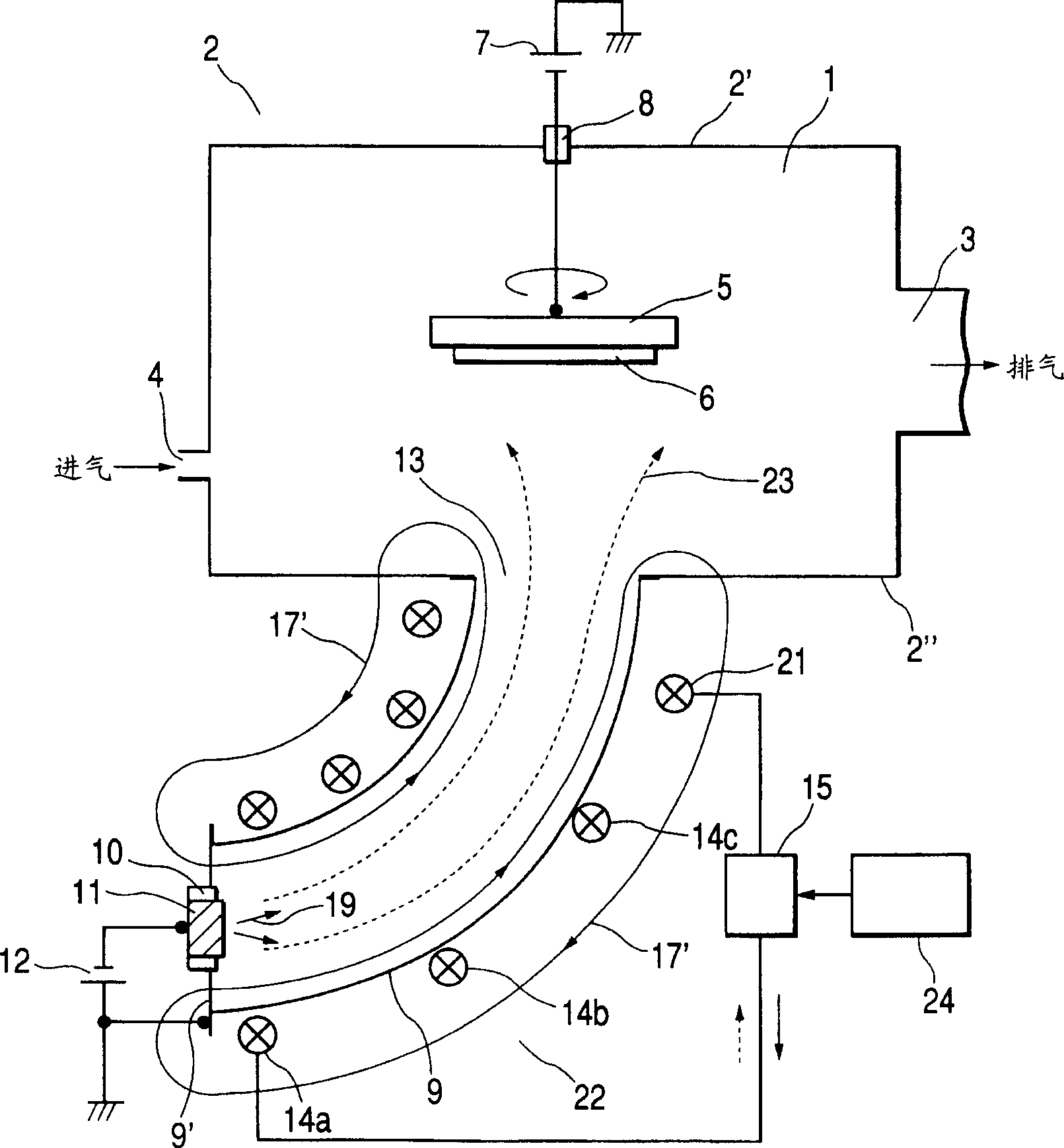
[0155] Refer to the attached figure 1 -8 An embodiment of the present invention will be described.

[0156] figure 1 for with Figure 9 The plan view of the corresponding vacuum arc evaporation apparatus in the vacuum arc evaporation apparatus.

[0157] exist figure 1 , replace with electromagnetic coil 21Figure 9 In the electromagnetic coil 14d as the end magnet. This electromagnetic coil 21 is larger than the other electromagnetic coils 14a-14c.

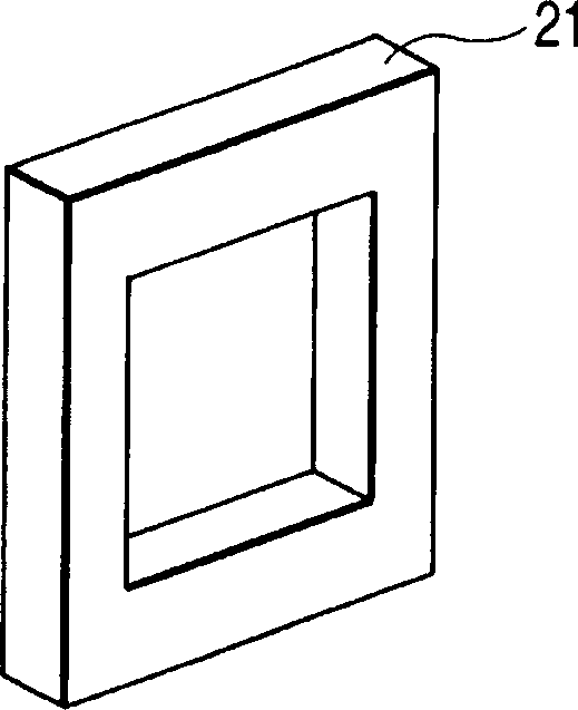
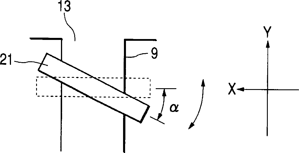
[0158] The shape of the electromagnetic coil 21 is similar to figure 2 Medium rectangular frame shown in perspective view. In the representation installed to Figure 3A and 3B In the plan view and right side view of the electromagnetic coil on the tube in , the X-axis direction represents the horizontal direction (the right side is the "positive direction"), the Y-axis direction is the front-back direction (the rear side is the "positive direction"), and the Z-axis direction The direction is the vertical direction (uppe...


PUM


Abstract

To prevent the film forming characteristic deterioration by a magnetic field of a magnetic filter to thereby make vacuum arc vapor deposition uniform, in the invention, plurality of magnets includes a terminal magnet closest to a plasma injection hole located at the other end of duct and specified magnets. The terminal magnet located closest to plasma injection hole may be set to incline to a plasma injection plane of the plasma injection hole. Further, at lease one of specified magnets may be inclined to the plasma injection plane. Further more, at least one of magnetic field generating coils may be formed with a plurality of electromagnetic coils, which are inclined at different angles with respect to a cross section of the duct. One of electromagnetic coils may be selectively energized by current on a basis of setting and controlling of deflection magnetic field generated by the magnetic filter.

Description

technical field [0001] The invention relates to a vacuum arc evaporation method and device, which are used to form a thin film on the surface of a substrate to improve the wear resistance of the substrate. The substrate can be used as automobile parts, machine parts, machine tools, and metal moulds, especially relating to the generation and control of magnetic fields by means of magnetic filters. Background technique [0002] In general, vacuum arc evaporation is a simple thin film forming method in which an arc discharge is generated between a cathode and an anode, and a cathode material is evaporated to deposit on a substrate to form a thin film thereon. Thin films can be efficiently produced by this method. [0003] However, in the vacuum arc evaporation method, large particles (droplets) having a diameter of several μm are emitted from the cathode (and also from the anode in some cases of electric discharge). Then, as is known, the droplets are deposited on the substra...

Claims


Application Information

Patent Timeline
Patent Type & Authority Applications(China)
IPC IPC(8): C23C14/24C23C14/32H01J37/32
CPCH01J2237/022C23C14/325H01J37/32055C23C14/24
Inventor 村上泰夫三上隆司绪方洁村上浩
Owner NISSIN ELECTRIC CO LTD
Why Eureka
Try Eureka