Blowing system of chain boiler with sectorial blow homogenating plate

A chain boiler and air distribution system technology, which is applied in the direction of furnace grate, mobile furnace grate, combustion air/fuel supply, etc., to achieve the effects of reducing airflow deviation, fully burning coal, and increasing combustion temperature

Inactive Publication Date: 2003-06-18
SHANGHAI JIAO TONG UNIV
View PDF0 Cites 10 Cited by
  • Summary
  • Abstract
  • Description
  • Claims
  • Application Information

AI Technical Summary

Problems solved by technology

[0003] The purpose of the present invention is to provide a chain boiler air distribution system with a fan-shaped air equalizer to reduce th

Method used


Image

  • Blowing system of chain boiler with sectorial blow homogenating plate
  • Blowing system of chain boiler with sectorial blow homogenating plate
  • Blowing system of chain boiler with sectorial blow homogenating plate

Examples


Embodiment Construction

[0014] The technical solution of the present invention will be further described below in conjunction with the accompanying drawings.

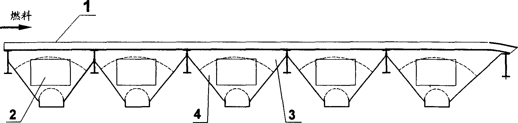
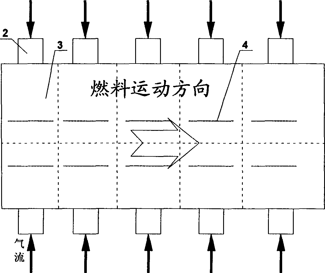
[0015] The chain boiler air distribution system structure of the present invention is as follows: figure 1 , figure 2 shown. Considering factors such as falling ash, the cross section of the air chamber 3 is a trapezoidal shape with a large upper part and a smaller lower part, and a fan-shaped air equalizing plate 4 is installed in the air chamber 3. The air equalizing plate is inserted into the air chamber, and its plane is perpendicular to the direction of air flow. It is welded to the two walls of the air chamber and does not touch the ash bucket at the bottom of the air chamber, so it will not affect the ash fall.

[0016] The fan-shaped air distribution plate can be a thin steel plate with a thickness of 5mm.

[0017] The air used for combustion enters the air chamber 3 from the air inlet pipe 2, passes through the fire grate 1 in the...


PUM


Abstract

A air distribution system in chain with fan shaped plate to make air even for boiler includes air chamber, fire grate and wind introducing pipe. According to structure and feature of the air chamber, the fan shaped plate to make air even and to be suitable to the air chamber will be designed and erected in different locations of the air chamber, but it will not knock against with dust collector set at bottom of the air chamber with its plane in vertical to direction of air flowing. The present invention can decrease air flow deviation along with width direction of the boiler a lot so as to decrease air amount of once a time for raising combustion temperature in the boiler and the boiler efficiency.

Description

Technical field: [0001] The invention relates to an air distribution system for a chain boiler, in particular to an air distribution system for a chain boiler with a fan-shaped air equalizing plate, which is applied to a firebed combustion chain boiler and relates to the fields of chemical industry, energy and light industry. Background technique: [0002] The existing fire bed combustion chain boiler air distribution system uses the air boxes on both sides of the boiler to introduce the air required for combustion into the air chamber under the chain grate for ventilation and air distribution. The air volume adjustment in the grate movement direction is adjusted through the baffles of each air duct. However, in the direction perpendicular to the movement of the grate, the air distribution through the warehouse is adopted, so there is no means of adjusting the air volume in this direction, which will cause uneven air supply in this direction on the grate, and some local air ...

Claims


Application Information

Patent Timeline
IPC IPC(8): F23H11/10F23L1/02
Inventor 陆方罗永浩
Owner SHANGHAI JIAO TONG UNIV
Why Eureka
Try Eureka