Catalytic cracking method and apparatus

A catalytic cracking and catalyst technology, applied in the direction of catalytic cracking, cracking, petroleum industry, etc., can solve the problems of overall activity reduction, lack of flexibility in adjustment, etc., and achieve the goal of reducing local temperature, improving product distribution and product properties, and great flexibility Effect

Active Publication Date: 2007-09-19
SINOPEC LUOYANG PETROCHEM ENG CORP
View PDF2 Cites 31 Cited by
  • Summary
  • Abstract
  • Description
  • Claims
  • Application Information

AI Technical Summary

Problems solved by technology

[0004] The technical problem to be solved by the present invention is: the overall activity of the mixed catalyst caused by the mixing mode of the standby catalyst and the regenerated catalyst of the above-mentioned existing double-riser catalytic cracking unit participates in the reaction of the heavy oil riser reactor, and the reaction to the heavy oil The problem of lack of flexibility in the adjustment of the agent-oil ratio of the riser reactor

Method used


Image

  • Catalytic cracking method and apparatus
  • Catalytic cracking method and apparatus

Examples


Embodiment 1

[0029] According to the comparative example, the difference is the weight mixing ratio of the stripped spent catalyst from the light hydrocarbon riser reactor and the regenerated catalyst from the regenerator in the catalyst mixing tank, the temperature of the mixed catalyst in the catalyst mixing tank, and the lift of heavy oil The agent-to-oil ratio, refining ratio and reaction time of the tube reactor. Table 4 shows the operating conditions, product distribution and partial properties of the gasoline produced in the heavy oil riser reactor of this example.

Embodiment 2

[0031] According to the comparative example, the difference is the weight mixing ratio of the stripped spent catalyst from the light hydrocarbon riser reactor and the regenerated catalyst from the regenerator in the catalyst mixing tank, the temperature of the mixed catalyst in the catalyst mixing tank, and the lift of heavy oil The agent-to-oil ratio, refining ratio and reaction time of the tube reactor. The operating conditions, product distribution and some properties of the gasoline produced in the heavy oil riser reactor of this example are shown in Table 5.

Embodiment 3

[0033] According to the comparative example, the difference is the weight mixing ratio of the stripped spent catalyst from the light hydrocarbon riser reactor and the regenerated catalyst from the regenerator in the catalyst mixing tank, the temperature of the mixed catalyst in the catalyst mixing tank, and the lift of heavy oil The agent-to-oil ratio, refining ratio and reaction time of the tube reactor. The operating conditions, product distribution and partial properties of the gasoline produced in the heavy oil riser reactor of this example are shown in Table 6.


PUM

PropertyMeasurementUnit
lengthaaaaaaaaaa

Abstract

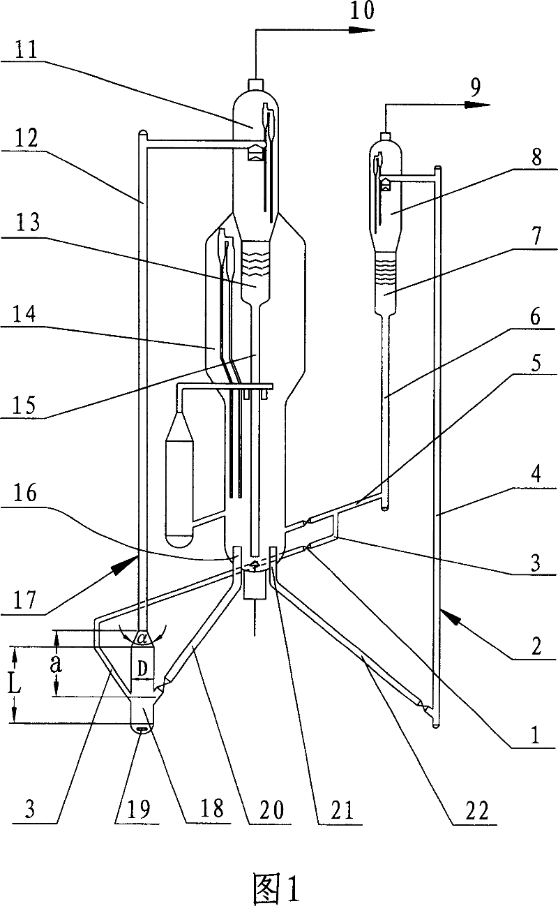
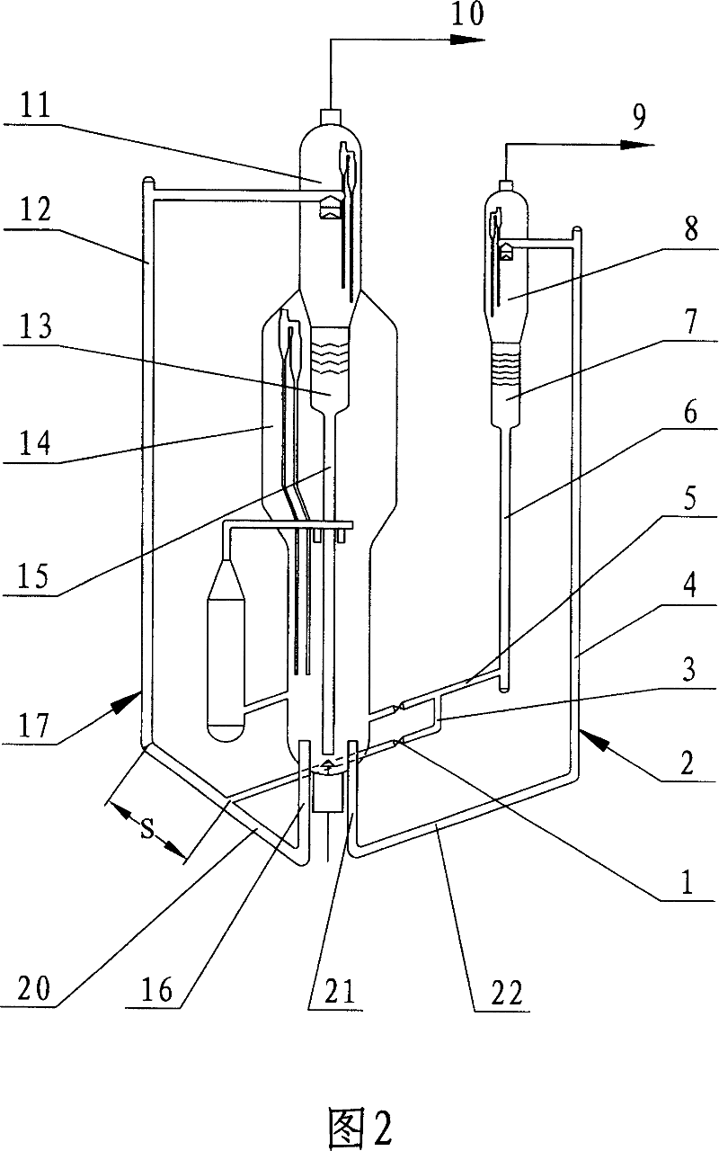
The invention discloses a kind of catalysis crack method and its device in petroleum chemical industry, to solve the problems as the whole activeness reduction of mixed catalysts and the flexibility lack of adjusting the agent-oil proportion of heavy oil riser reactor caused by the mixing wise of the spend catalyst and regenerating catalyst of the present two-riser catalysis crack device. The main characteristics of the invention method are: part of the spent catalyst from the light hydrocarbon riser reactor (4) gets into catalyst mixer through the spent catalyst duct (3) set flow control valve (1) after water vapour stripped in the stripping section (7) of the second settler, and gets into heavy oil riser reactor (12) to react after mixed by the effect of water vapour with the regenerating catalyst form regenerator (14) in catalyst mixer. The method of the invention is suitable to be used in the two-riser catalysis crack craft and the three-riser catalyst crack craft set heavy oil riser reactor; the invention has disclosed related devices.

Description

Technical field [0001] The invention belongs to the field of petrochemical catalytic cracking, and particularly relates to a catalytic cracking method and device using two or three riser reactors. Background technique [0002] At present, a dual riser catalytic cracking unit used in the catalytic cracking process of the petrochemical industry is equipped with a heavy oil riser reactor and a light hydrocarbon riser reactor, and the three riser catalytic cracking unit also has a heavy oil reformer. Quality riser reactor; the outlets at the top of each riser reactor are respectively connected with their respective settlers, and the bottom is connected with the regenerator through respective regeneration inclined pipes and regeneration risers. In the above-mentioned catalytic cracking unit, the regeneration temperature of the catalyst is generally higher than 650°C. Due to the high temperature of the regenerated catalyst and the limitation of the thermal balance of the device, the ca...

Claims


Application Information

Patent Timeline
Patent Type & Authority Patents(China)
IPC IPC(8): C10G11/02
Inventor 陈曼桥王文柯闫鸿飞李玖云刘金龙汤海涛
Owner SINOPEC LUOYANG PETROCHEM ENG CORP
Why Eureka
Try Eureka