
Two-dimensional microvibration optical fibre test system and method

An optical fiber detection and two-dimensional optical fiber technology, which is applied to measurement devices, optical devices, image data processing, etc., can solve the problems of complex receiving equipment, low sensitivity, and inconvenient use, and achieve the effect of simple manufacturing and structure.

Inactive Publication Date: 2003-06-18
JIABEI PHOTOELECTRIC IND RES SHANGHAI
View PDF0 Cites 2 Cited by
  • Summary
  • Abstract
  • Description
  • Claims
  • Application Information

AI Technical Summary

Problems solved by technology

However, this patented technology has obvious defects. Because it uses a grating, the sensitivity is not high, and it cannot detect 1×10 -5 Meter-level vibration, and its receiving equipment is too complicated, inconvenient to use, and not conducive to computer analysis and recording

Method used


Image

  • Two-dimensional microvibration optical fibre test system and method
  • Two-dimensional microvibration optical fibre test system and method
  • Two-dimensional microvibration optical fibre test system and method

Examples


Embodiment Construction

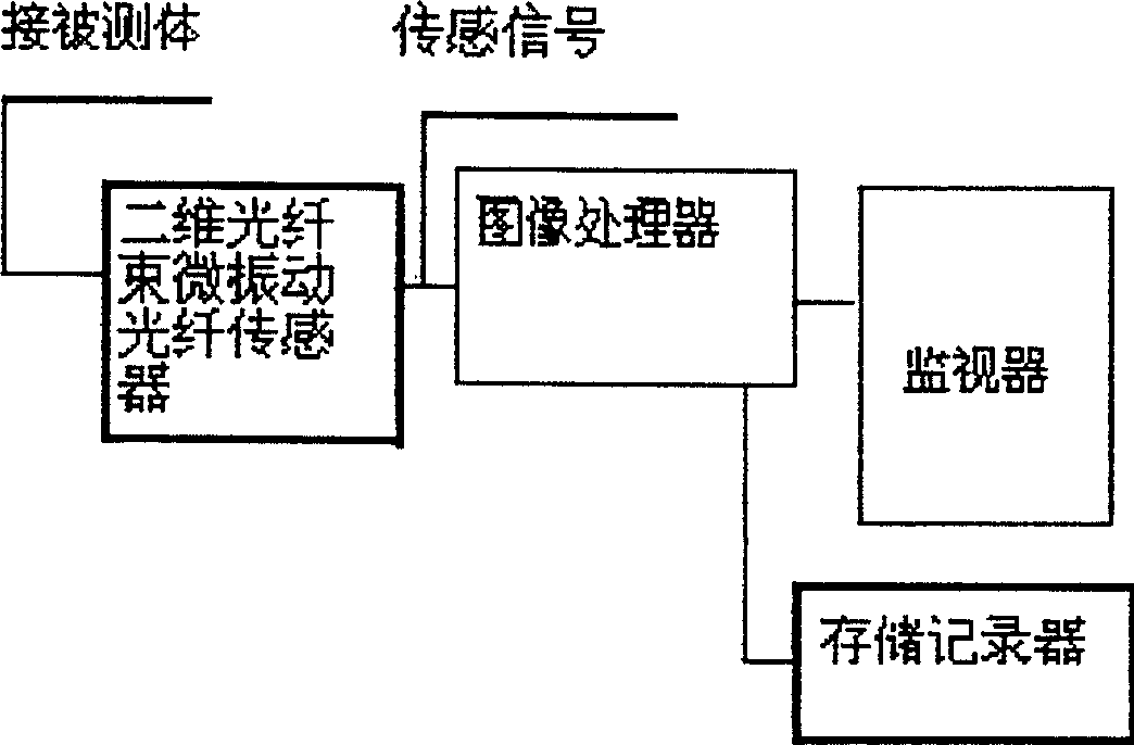
[0012] According to attached figure 1 In the two-dimensional micro-vibration optical fiber detection system, the two-dimensional optical fiber bundle micro-vibration optical fiber sensor placed on the measured object outputs the sensing signal to the image processor, and the image processor compares the sensing signal with the set standard signal for processing Then output to the monitor and memory recorder.

[0013] Install the two-dimensional optical fiber bundle micro-vibration optical fiber sensor on the vibrating body to be detected, and input the signal to image processing through the two-dimensional micro-vibration optical fiber sensor, and the quantitative signal after image processing is sent to the monitor and storage recorder, when the vibrating body When the vibration frequency of the fiber is close to the natural frequency of the fiber, the fiber will resonate, and it can be clearly seen on the monitor that the above-mentioned light spots will change with the ampl...


PUM


Abstract

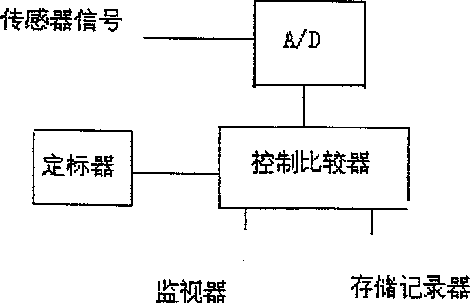
A detection system of optical fibre with two-dimentional microvibration consists of optical fibre transducer of microvibration in two-dimentional optical fibre bundle, picture processor to process transducing signal transmitted from the optical fibre transducer of microvibration in two-dimentional optical fibre bundle and monitor as well as storing recorder to receive signal transmitted from the picture processor. The test method is as follows: to set the optical fibre transducer of microvibration in two-dimensional optical fibre bundle on the object to be tested, to turn on power of picture switching device of the transducer, to set standard signal for calibrator, to carry on comparison of transducing signal with standard signal by the picture processor and then to send it to the monitor and the storing recorder for on-line detection.

Description

1. Technical field: [0001] The invention relates to a vibration detection system, in particular to a two-dimensional micro-vibration optical fiber detection system and a testing method. 2. Background technology: [0002] When large-scale instruments and equipment are working, there will be a certain range of small vibrations. Under normal circumstances, the amplitude of this vibration will not exceed a certain range. When equipment such as equipment and operation work abnormally, the vibration will also appear abnormal. In many cases, we hope to know the specific size and direction of this vibration, so as to obtain the critical value of abnormal vibration immediately, and take measures to rule out major accidents in equipment, flight and operation. [0003] In the early days of measuring vibration displacement, levers or gears / racks were used to amplify. This type of meter has disadvantages such as wear, inconvenient reading, and inability to transmit vibration signals. A...

Claims


Application Information

Patent Timeline
Patent Type & Authority Applications(China)
IPC IPC(8): G01B11/04G06T1/00
Inventor 陈世祥殷宗敏周正利曹其美
Owner JIABEI PHOTOELECTRIC IND RES SHANGHAI
Learn More