
Power conversion apparatus with frequency operation change based on input voltage

a technology of power conversion apparatus and input voltage, which is applied in the direction of electric variable regulation, process and machine control, instruments, etc., can solve the problems of high frequency inverter, wide voltage range variation, switching loss, etc., and achieve the effect of reducing the size preventing the decrease of the efficiency of the power conversion apparatus

Active Publication Date: 2018-02-06
HITACHI LTD
View PDF17 Cites 0 Cited by
  • Summary
  • Abstract
  • Description
  • Claims
  • Application Information

AI Technical Summary

Benefits of technology

[0008]For example, the voltage variation of the solar power generation is a maximum power point tracking (MPPT) voltage range by weather and an increase of the voltage by an open circuit voltage (OCV) when an output is stopped. For the DC / DC converter and the inverter within the PCS, an electrolytic capacitor and a film capacitor are used. If the voltage is increased, a high voltage-resistant capacitor is used so as not to exceed a rated voltage of the capacitor. Since capacitance and an allowable ripple current value of the capacitor are decreased as the capacitor is high voltage-resistant even at the same size, it is preferable that the rated voltage is decreased to reduce the size and the weight of the capacitor.
[0011]It is possible to prevent a decrease of efficiency of the power conversion apparatus while reducing the size of the power conversion apparatus.

Problems solved by technology

In order to realize a reduction in size and weight of the PCS, if the SST is applied to the PCS, there is a problem that variation of a wide range of the voltage such as the solar power generation and switching loss of a power device that is used in the power circuit such as the DC / DC converter and the inverter for the high frequency occur.
The IGBT is a device suitable for high voltage-resistance, switching thereof is practical at several kHz, and there is a problem that switching loss occurs in driving at several tens of kHz.

Method used


Image

  • Power conversion apparatus with frequency operation change based on input voltage
  • Power conversion apparatus with frequency operation change based on input voltage
  • Power conversion apparatus with frequency operation change based on input voltage

Examples


example 1

[0024]In the example, as an example of a power conversion apparatus, a PCS that converts DC power from a solar power generation device (hereinafter, solar power generation) into AC power and outputs AC power to a system will be described.

[0025]First, a configuration of the example is described below.

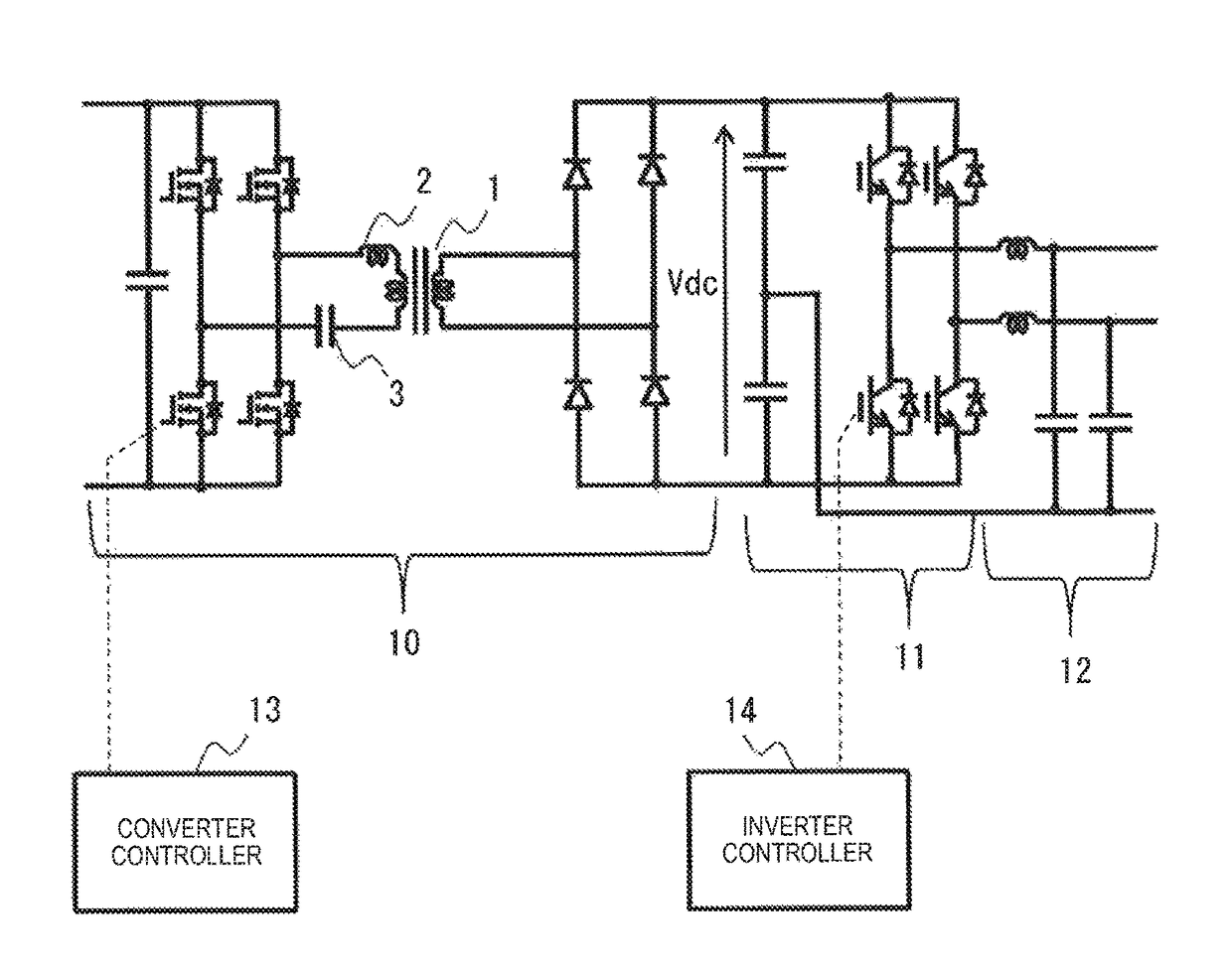
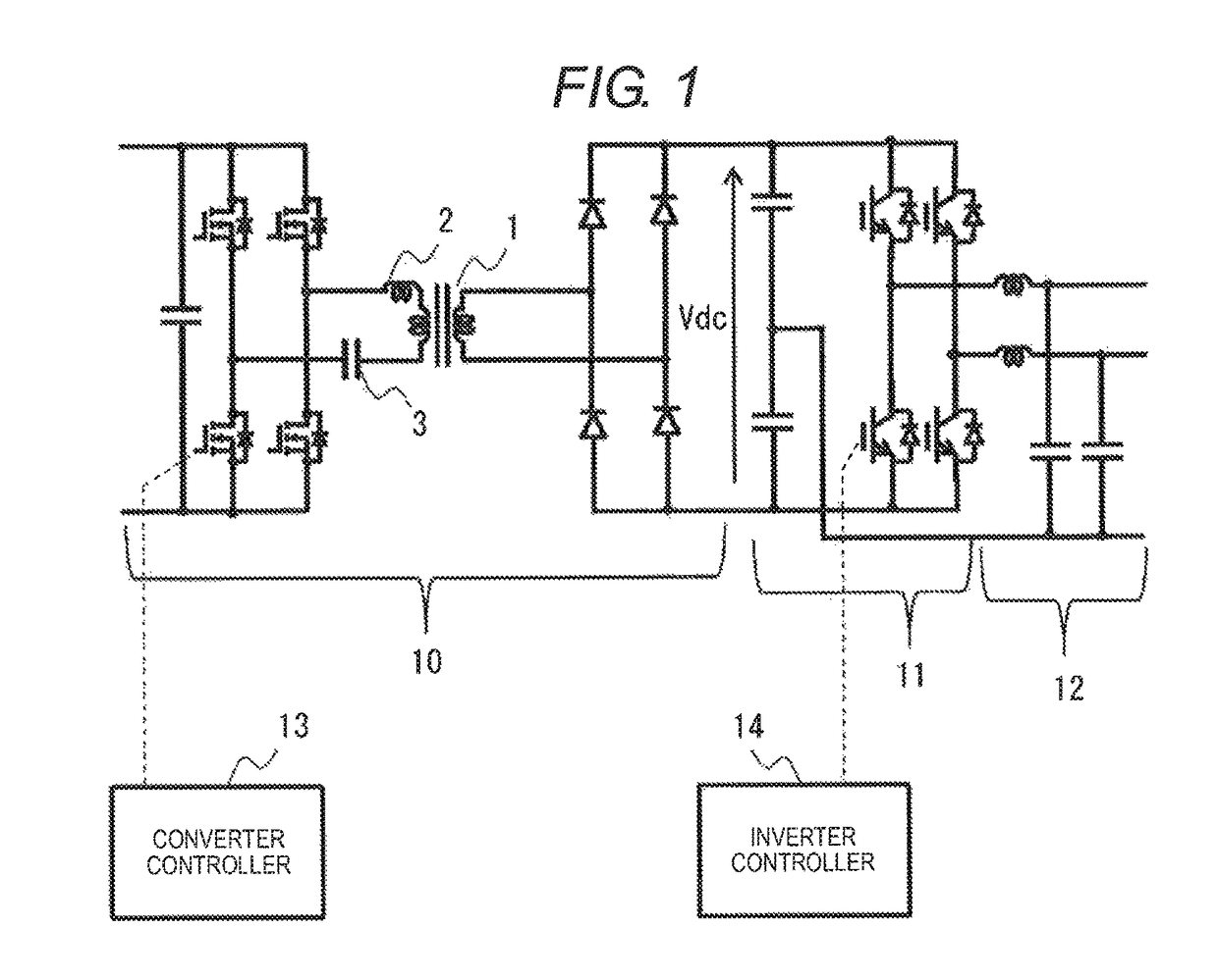
[0026]FIG. 1 illustrates a configuration of the PCS of Example 1.

[0027]The example is assumed to be a PCS of a class of several kW to several tens of kW interconnecting to a low voltage (for example, a system of 100 V and 200 V). The PCS includes an H-bridge type LLC resonant DC / DC converter (hereinafter, referred to as an LLC resonant converter) 10, an inverter 11, an output filter 12, a converter controller 13, and an inverter controller 14.

[0028]The LLC resonant converter 10 is connected to the solar power generation and receives DC power from the solar power generation. The LLC resonant converter 10 includes a high frequency transformer 1, converts a voltage of DC power, and outputs ...

example 2

[0060]FIG. 9 illustrates a configuration of a PCS of Example 2.

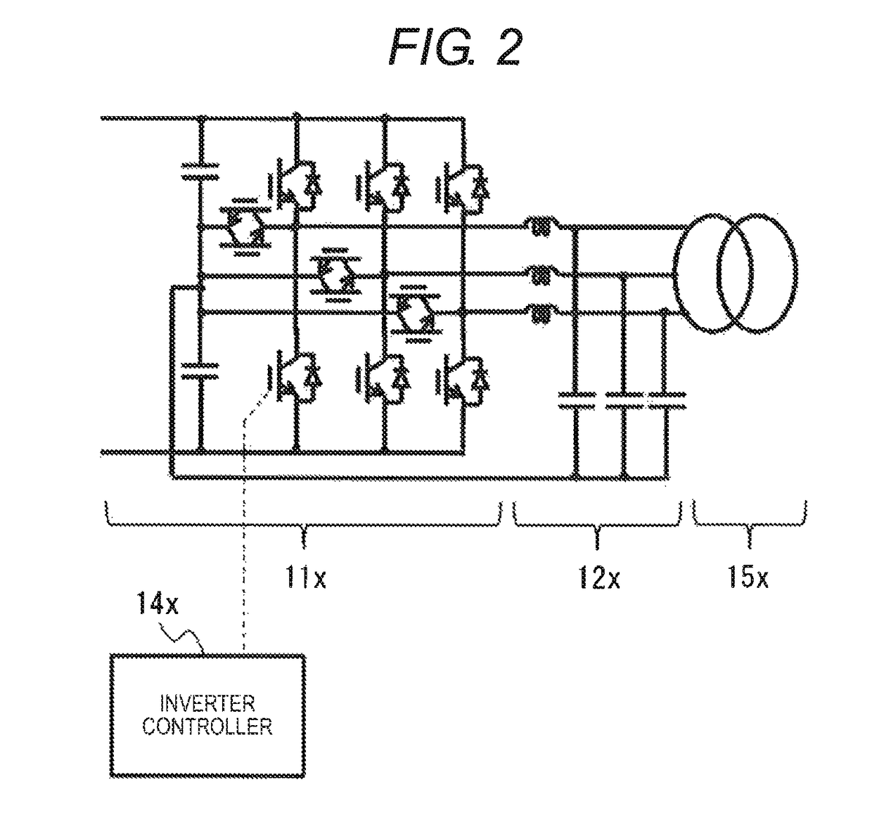
[0061]The example is assumed to be the PCS of a class of several hundreds of kW interconnecting to a high voltage (for example, a system of 6.6 KV). In the PCS of the example, elements to which the same reference numerals as those of the elements of the PCS of Example 1 are given are the same or corresponding elements and description thereof will be omitted. When compared to the PCS of Example 1, the PCS of the example includes an inverter 11d instead of the inverter 11, includes a converter controller 13d instead of the converter controller 13, and an inverter controller 14d instead of the inverter controller 14. The inverter 11d is a three-phase and three-level inverter, and includes four driving elements for one phase. The inverter controller 14d performs PWM control of the inverter 11d. Thus, it is possible to further reduce switching loss.

[0062]If a primary side input maximum voltage of an H-bridge type LLC resonant...


PUM


Abstract

If an input voltage of a DC / DC converter is lower than a first voltage value that is set in advance, a converter controller maintains an output voltage of the DC / DC converter within a first voltage range that is set in advance by changing an operation frequency of switching of the DC / DC converter in compliance with the input voltage as a first voltage maintaining control. If the input voltage is higher than a second voltage value that is higher than the first voltage value, the converter controller maintains the output voltage within a second voltage range that is higher than the first voltage range by changing the operation frequency in compliance with the input voltage as a second voltage maintaining control.

Description

BACKGROUND OF THE INVENTION[0001]Field of the Invention[0002]The present invention relates to a power conversion apparatus.[0003]Background Art[0004]Since an insulated transformer for system interconnection is driven with a low frequency of several tens of Hz that is the same as a system frequency, there is a problem that a reduction in size and weight is difficult. In recent years, a solid-state transformer (SST) has been studied to apply to a high-voltage and high-power application. The SST has a high frequency transformer and a power circuit such as a DC / DC converter that outputs an alternating current of the system frequency by driving the high frequency transformer, and can substitute for a low frequency transformer of the related art. The high frequency transformer is driven with the high frequency of several tens of Hz to several hundreds of kHz and then it is possible to reduce the size of the high frequency transformer and to realize a significant reduction in size and weig...

Claims


Application Information

Patent Timeline
Patent Type & Authority Patents(United States)
IPC IPC(8): H02M3/335H02M1/32H02M7/48H02M5/458H02M7/487
CPCH02M5/458H02M1/32H02M7/4807H02M3/335Y02B70/1433H02M7/487G05F1/67H02J3/383H02M3/33507H02M1/0054Y02B70/10Y02E10/56
Inventor NORIMATSU, YASUAKIKANOUDA, AKIHIKOMABUCHI, YUUICHICHIDA, TADAHIKOISHIGAKI, TAKUYASHIMADA, TAKAE
Owner HITACHI LTD
Learn More