Display device and driving method thereof

A technology of display panel and display electrode, which is applied in the direction of AC plasma display panel, floating electrode, electrode configuration, etc., can solve the problem of reduced brightness of pulsed light emission

Inactive Publication Date: 2003-06-18
HITACHI LTD
View PDF2 Cites 14 Cited by
  • Summary
  • Abstract
  • Description
  • Claims
  • Application Information

AI Technical Summary

Problems solved by technology

However, low drive current will reduce the luminous brightness of each pulse

Method used


Image

  • Display device and driving method thereof
  • Display device and driving method thereof
  • Display device and driving method thereof

Examples


Embodiment Construction

[0047] Hereinafter, preferred embodiments of the present invention will be described with reference to the accompanying drawings.

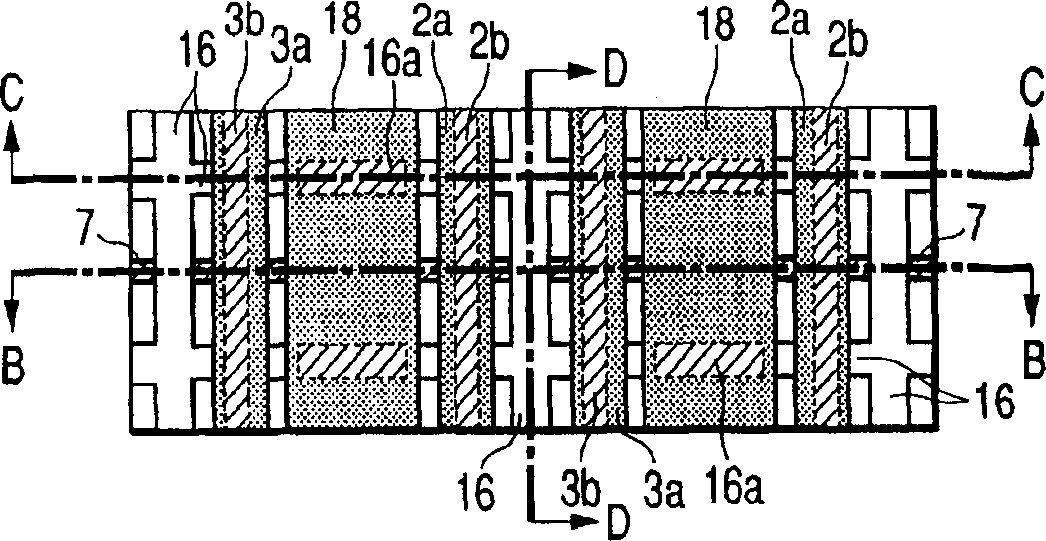
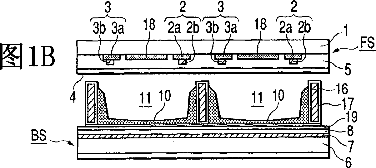
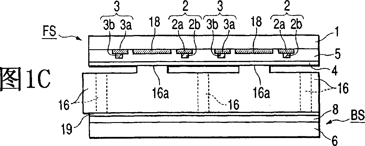
[0048] Figure 1A is a plan view of the plasma display panel according to the first embodiment of the present invention, seen from the side of the front panel. Figures 1B, 1C and 1D are in Figure 1A , the cross-sectional views taken along the line segment B-B, line segment C-C and line segment D-D respectively. exist Figures 1A to 1D In, shown are the metal barrier ribs 16, the protrusions 16a protruding from the metal barrier ribs 16, the intermediate electrodes 18, the protective layer 19 made of a magnesium oxide (MgO) film or the like, and a cavity. 20. exist Figures 1A to 1D , use the same reference characters to denote the following Figure 12 and 16 Similar or corresponding components are omitted, and their descriptions are omitted to avoid repetition.

[0049] With reference to Fig. 1, by corresponding to each cell discharge spac...


PUM


Abstract

An intermediate electrode is formed in a space between an X display electrode and a Y display electrode parallel thereto. A negative voltage is applied to the Y display electrode to use the Y display electrode as a cathode. A charge is stored between the Y display electrode and an intermediate electrode to create an electric field. Upon the increase of the intensity of the electric field to a sufficiently high level, an instant discharge occurs between the Y display electrode and the X display electrode and intense ultraviolet rays are produced. The fluorescent layer excited by the ultraviolet rays emits visible light. Only a narrow pulse current flows through the X display electrode and the Y display electrode, so that power consumption can be suppressed at high emission efficiency.

Description

technical field [0001] The invention relates to a plasma display panel, which is used in information processing terminals and various flat wall-mounted TV sets, and a display using the plasma display panel. Specifically, the present invention relates to a plasma display panel capable of operating with greatly improved luminous efficiency and capable of displaying images with greatly improved luminance, and to a plasma display panel using such a plasma display panel monitor. Background technique [0002] A reflective three-electrode surface discharge plasma display panel has been widely used, on which two types of transparent display electrodes formed on the same surface of a front substrate are provided. A prior art reflective three-electrode surface discharge plasma display panel is disclosed in the patent document JP 10-207419A. [0003] refer to Figure 12 , which shows a part of a known plasma display in a perspective view, showing a front substrate FS, a rear substrat...

Claims


Application Information

Patent Timeline
Patent Type & Authority Applications(China)
IPC IPC(8): G09G3/20G09G3/288G09G3/291G09G3/292G09G3/293G09G3/294G09G3/296H01J11/12H01J11/16H01J11/22H01J11/24H01J11/26H01J11/30H01J11/32H01J11/34H01J11/38H01J11/42H04N5/66
CPCG09G3/2927H01J11/28H01J11/32G09G2320/0238G09G3/2986H01J11/12H01J2211/326H01J11/36G09G2320/0228G09G3/2022G09G3/2935G09G3/2942G09G3/2932H01J2211/366G09G3/296H01J11/34
Inventor 秋庭丰
Owner HITACHI LTD
Why Eureka
Try Eureka