Automatic feeding riveter

A technology of automatic feeding and riveting machines, applied in the field of automatic feeding riveting machines, can solve the problems of low production efficiency, accidental injuries to operators, expensive diss hydraulic presses, etc., and achieve the effect of simple structure

Inactive Publication Date: 2003-06-25
HONG FU JIN PRECISION IND (SHENZHEN) CO LTD +1
View PDF0 Cites 26 Cited by
  • Summary
  • Abstract
  • Description
  • Claims
  • Application Information

AI Technical Summary

Problems solved by technology

[0002] In the modern machinery industry, it is necessary to use a large number of riveting processing technology to combine the corresponding components, but most of the riveting processing still adopts semi-automatic operation mode. The workpiece is placed on the riveting machine manually, and then pushed into the riveting station by The stamping mechanism of the riveting machine performs the riveting process by stamping, and then manually removes the workpiece from the riveting station and unloads the material. This processing method not only has low production efficiency, but also easily causes accidental injuries to the operator.
[0003] In order to effectively improve the efficiency of riveting processing, the industry has adopted an automatic riveting machine - Diss hydraulic press. This riveting machine can realize automatic feeding and unloading, which can effectively improve production efficiency and the product quality is acceptable, but The structure of this riveting machine is too complicated, the whole machine is bulky, and the energy consumption of the Diss hydraulic press is too large, and the Diss hydraulic press is relatively expensive, and the daily use cost is also high, so it cannot be used in large quantities.

Method used


Image

  • Automatic feeding riveter
  • Automatic feeding riveter
  • Automatic feeding riveter

Examples


Embodiment Construction

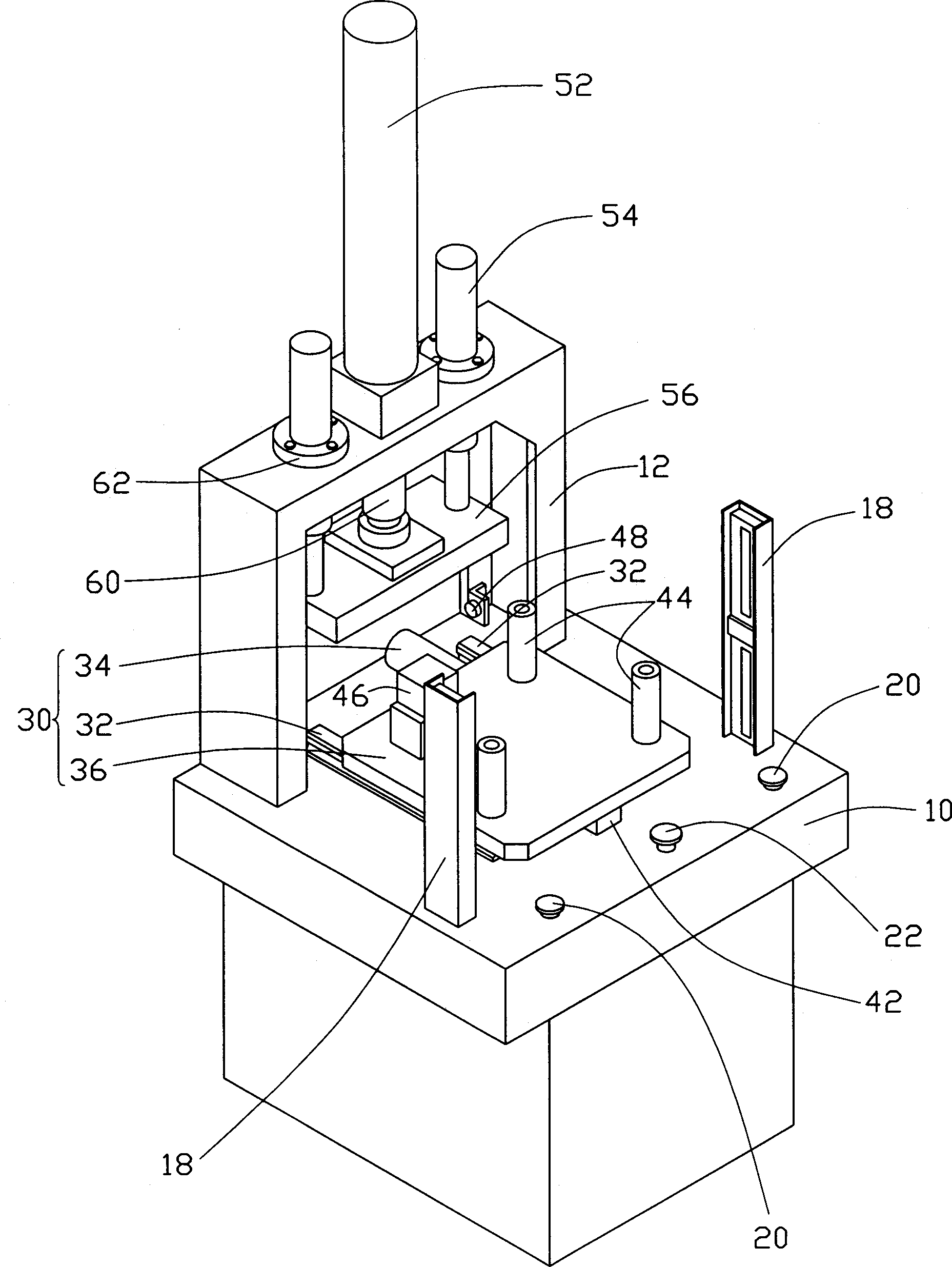
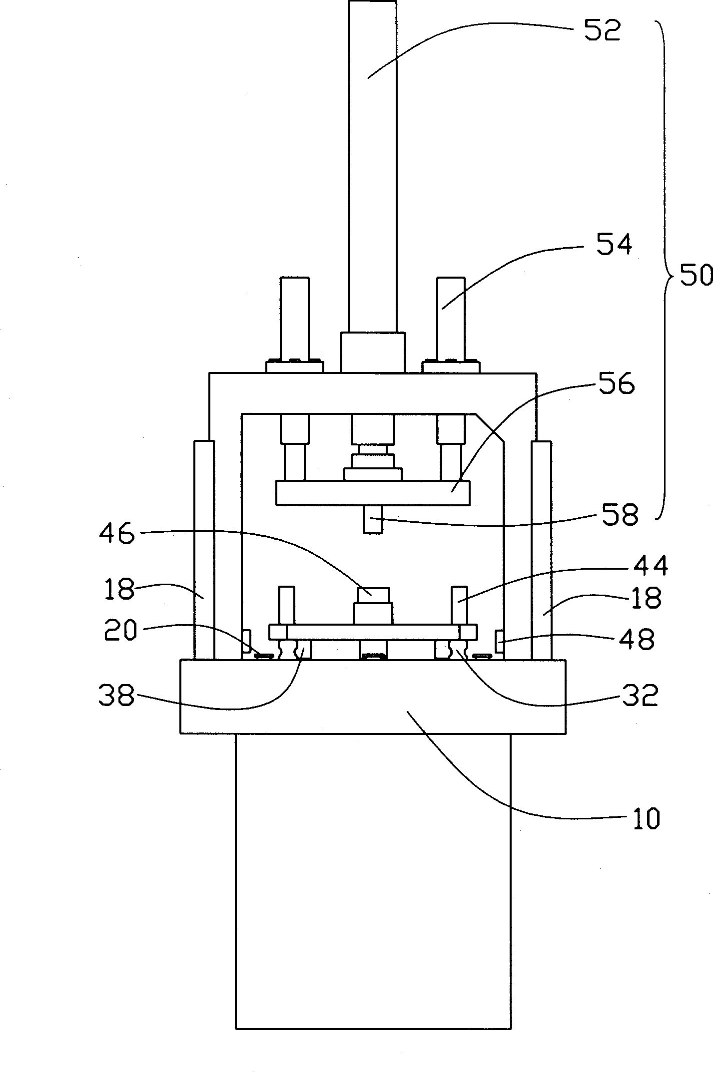
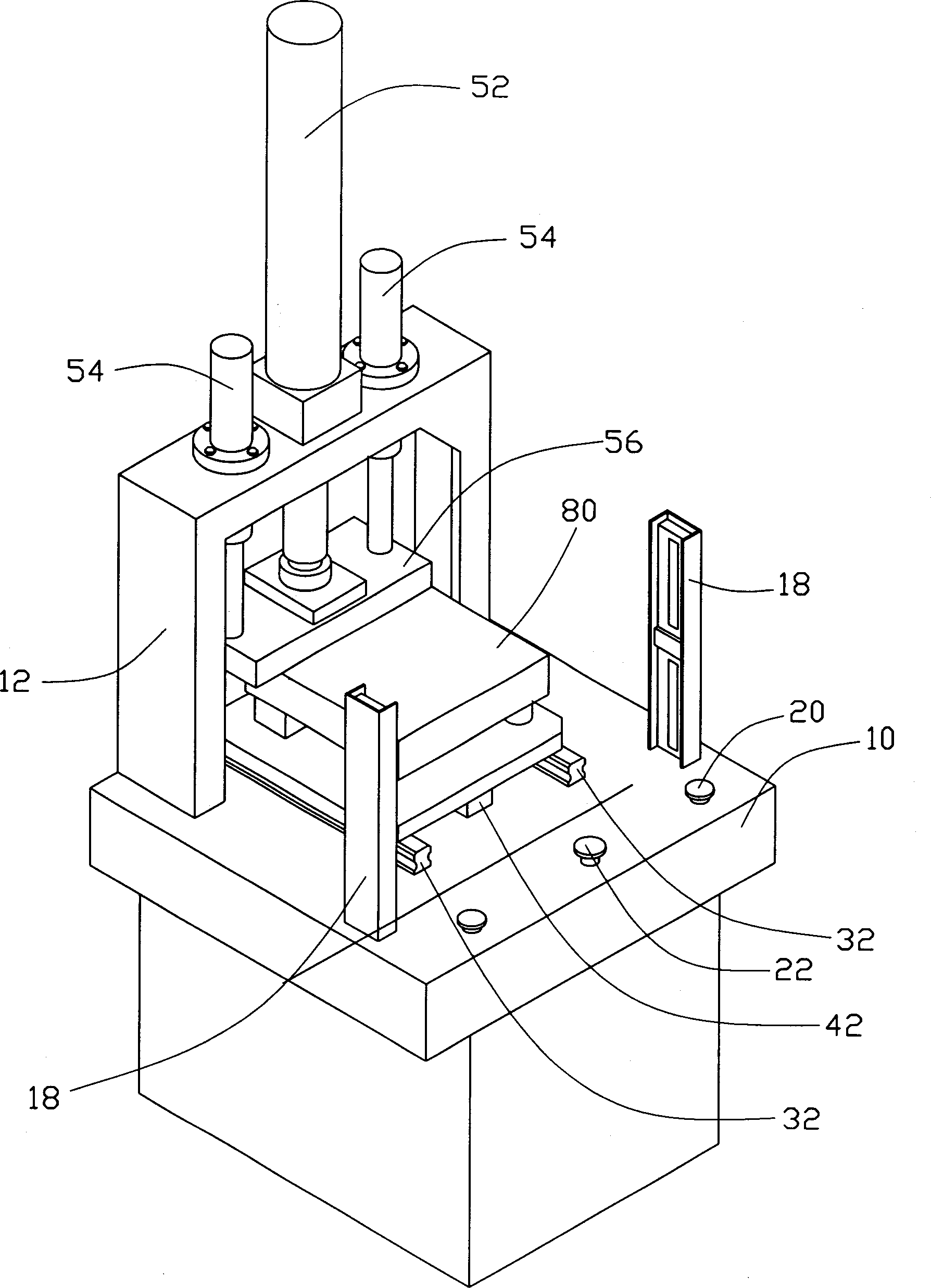
[0011] see figure 1 and figure 2 , The automatic feeding riveting machine of the present invention includes a base 10 , a feeding mechanism 30 and a riveting device 50 .

[0012] A ㄇ-shaped support frame 12 is vertically installed on the rear end of the upper surface of the base 10, and a photoelectric relay 18 is respectively installed on both sides of the front end of the base 10. When an object is blocked between the two photoelectric relays 18, the riveting Closed machine will not start to ensure the safety of the operator. The front edge of the base 10 is provided with a start button 20 on both sides and an emergency stop button 22 in the middle.

[0013] The feeding mechanism 30 includes two slide rails 32 arranged in parallel, a small air cylinder 34 and a lower template 36 . The two slide rails 32 are arranged on the middle part of the upper surface of the base 10, and they extend to the bottom of the support frame 12. The small cylinder 34 is installed between the...


PUM


Abstract

The automatic feeding riveter includes one base, one feeding mechanism and one riveting unit. On the base, there is a portal support installed vertically, two photoelectric relays on two sides of front part, two start buttons and one emergency stop button. The feeding mechanism includes two parallel slide racks, one small cylinder between the two slide racks and one lower template capable of sliding along the slide racks and one connecting block fixed to the end of piston rod of the small cylinder. One photoelectric contact is set on the inner wall of the portal support. The riveting unit includes one large cylinder, two guide columns, one connecting board and one riveting head connected together.

Description

【Technical field】 [0001] The invention relates to an automatic feeding riveting machine, in particular to an automatic feeding riveting machine capable of automatic feeding and returning. 【Background technique】 [0002] In the modern machinery industry, it is necessary to use a large number of riveting processing technology to combine the corresponding components, but most of the riveting processing still adopts semi-automatic operation mode. The workpiece is placed on the riveting machine manually, and then pushed into the riveting station by The stamping mechanism of the riveting machine performs riveting processing, and then manually removes the workpiece from the riveting station and unloads the material. This processing method not only has low production efficiency, but also easily causes accidental injuries to the operator. [0003] In order to effectively improve the efficiency of riveting processing, the industry has adopted an automatic riveting machine - Diss hydra...

Claims


Application Information

Patent Timeline
Patent Type & Authority Applications(China)
IPC IPC(8): B21J15/10
Inventor 李胜清何亚强孟召来
Owner HONG FU JIN PRECISION IND (SHENZHEN) CO LTD
Why Eureka
Try Eureka