Device for forming isolated ribs on screen of plane display device

A technology for flat panel displays and substrates, which is applied in the directions of devices for coating liquids on surfaces, jetting devices, liquid jetting devices, etc.

Inactive Publication Date: 2003-07-02
DAINIPPON SCREEN MTG CO LTD
View PDF1 Cites 1 Cited by
  • Summary
  • Abstract
  • Description
  • Claims
  • Application Information

AI Technical Summary

Problems solved by technology

Therefore, it is impossible to reduce the non-luminous area that does not contribute to light emission to increase the brightness of the plasma display

Method used


Image

  • Device for forming isolated ribs on screen of plane display device
  • Device for forming isolated ribs on screen of plane display device
  • Device for forming isolated ribs on screen of plane display device

Examples


Embodiment Construction

[0027]

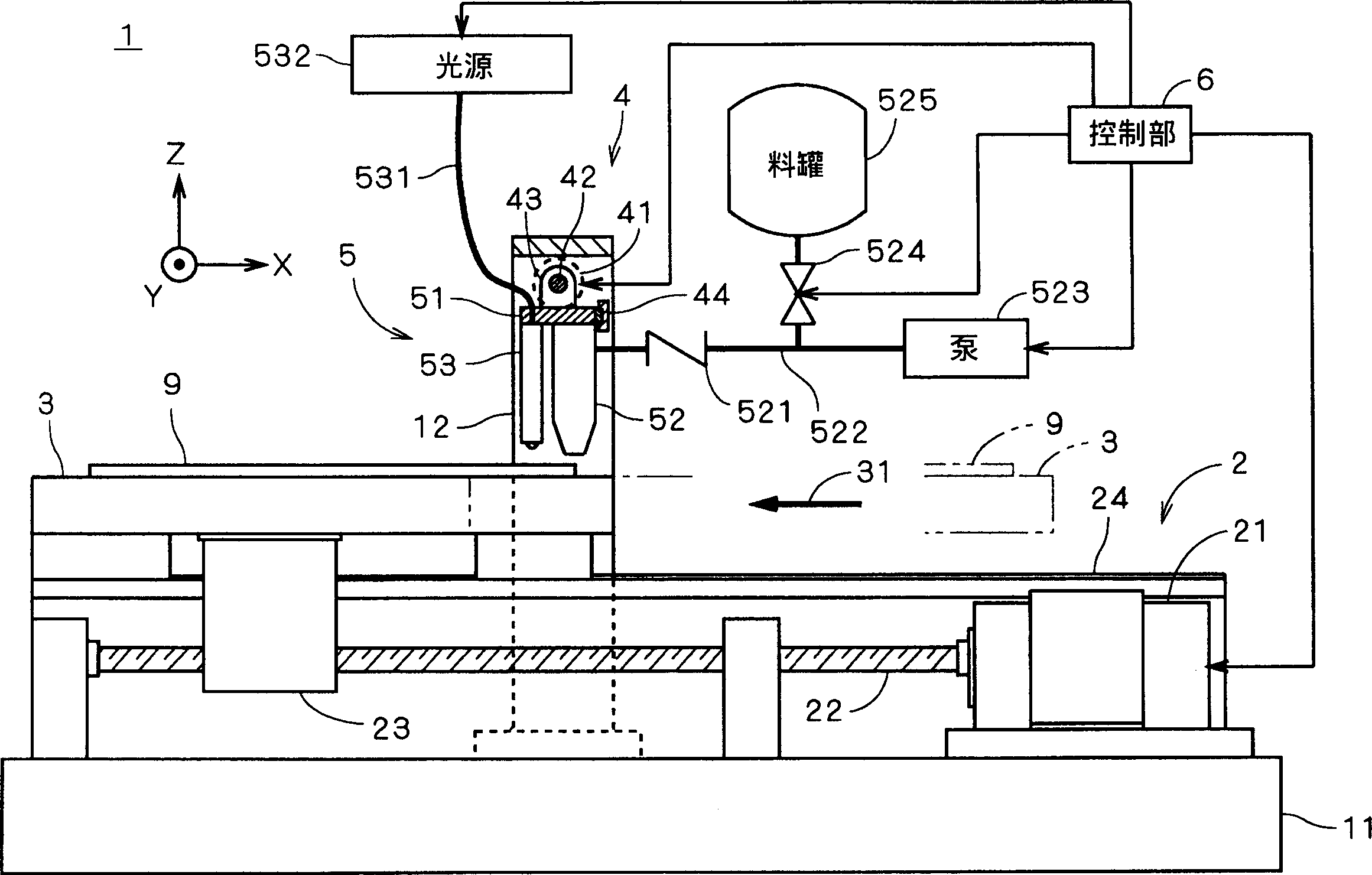
[0028] figure 1 is a view schematically showing the structure of the isolation rib forming device 1 according to the first preferred embodiment. The isolation rib forming device 1 is a device for forming isolation ribs on a glass substrate (called "substrate") 9 of a plasma display, and the substrate 9 on which the isolation ribs are formed becomes a screen plate (usually " Rear panel"), which is a sub-assembly of the plasma display.

[0029] In the isolation rib forming device 1, a platform transfer mechanism 2 is provided on the base 11, and the platform 3 supporting the substrate 9 can pass through the platform transfer mechanism 2 along the figure 1 to move in the X direction. The frame 12 is mounted on the base 11 across the platform 3 , and the head 5 is connected to the frame 12 via the swing mechanism 4 .

[0030] The platform transfer mechanism 2 has a structure in which a ball screw 22 is connected to a motor 21 and fitted into a nut 23 fixed on the pla...


PUM


Abstract

In a barrier-rib forming apparatus for forming barrier ribs on a substrate by discharging rib material from a discharge part, an oscillating mechanism for oscillating the discharge part in a direction perpendicular to a traveling direction of a stage which supports the substrate is provided to form barrier ribs of waveform on the substrate. The travel of the stage is performed twice, and at the second travel of the stage, each of barrier ribs is formed between adjacent ones of the already-formed barrier ribs. The barrier rib formed at the first travel of the stage and that formed at the second travel of the stage are disposed symmetrically to each other with respect to an axis parallel to the travel direction of the stage. With this formation of barrier ribs, it is possible to manufacture a panel which allows improvement in luminance of a plasma display.

Description

technical field [0001] The present invention relates to a technique for forming barrier ribs for panels of flat panel displays such as plasma displays and organic electroluminescent (EL) displays. Background technique [0002] Conventionally, barrier ribs have been formed on the rear panel of a plasma display by various methods. Among barrier rib forming methods known are sand blasting method, screen printing method, lift-off method, etc., and a method of forming barrier ribs by spraying rib material from nozzles has recently been proposed (for example, Japanese publication Patent JP9-92134). [0003] On the one hand, in a panel of a plasma display, light-emitting regions and non-light-emitting regions are alternately arranged in regions between barrier ribs. Later, in order to narrow the intervals of the barrier ribs in the non-light-emitting region, a technique of forming barrier ribs each in a wave shape by sandblasting was proposed. [0004] In the method of ejecting ...

Claims


Application Information

Patent Timeline
Patent Type & Authority Applications(China)
IPC IPC(8): H01J9/02H01J9/24H01J11/22H01J11/34H01J11/36
CPCH01J2211/36H01J9/242Y10T156/1705H01J9/24H01J11/36
Inventor 矢部学
Owner DAINIPPON SCREEN MTG CO LTD
Why Eureka
Try Eureka