Resistance discharging fluorescent lamp of planar medium

A dielectric barrier discharge, fluorescent lamp technology, applied in discharge lamps, gas discharge lamps, fluorescent lamps, etc., to reduce brightness differences, ensure stability, and improve brightness uniformity.

Inactive Publication Date: 2007-09-05
XI AN JIAOTONG UNIV
View PDF2 Cites 0 Cited by
  • Summary
  • Abstract
  • Description
  • Claims
  • Application Information

AI Technical Summary

Problems solved by technology

[0007] The object of the present invention is to provide a flat dielectric barrier discharge fluorescent lamp to solve the shortcomings of the flat fluorescent lamp in the prior art, thereby increasing the brightness of the flat fluorescent lamp, improving brightness uniformity, and increasing production efficiency

Method used


Image

  • Resistance discharging fluorescent lamp of planar medium
  • Resistance discharging fluorescent lamp of planar medium
  • Resistance discharging fluorescent lamp of planar medium

Examples


Embodiment Construction

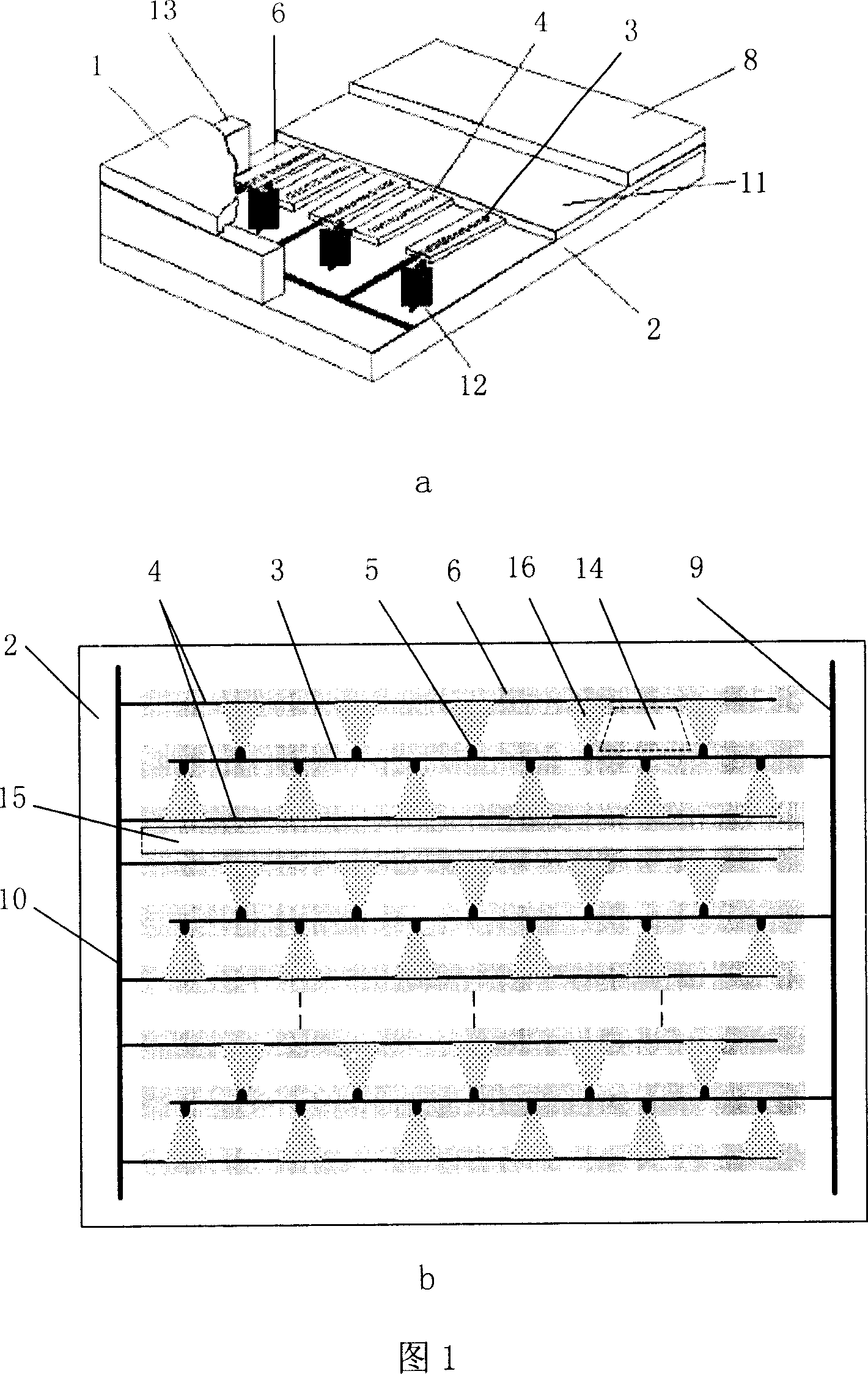
[0025] Fig. 1 is a schematic structural diagram of a planar dielectric barrier discharge fluorescent lamp in the prior art. It consists of a front glass substrate 1 and a rear glass substrate 2. The inner surface of the front glass substrate 1 is equipped with a phosphor layer, and the inner surface of the rear glass substrate 2 is equipped with two sets of electrodes—cathode and anode. The cathode is the X electrode 3. The anode is the Y electrode 4: the X electrode 3 and the Y electrode 4 are covered with a dielectric layer 6, and the surface of the dielectric layer 6 and the inner side of the rear glass substrate 2 not covered by the dielectric layer 6 are covered with a reflective layer 11. The reflective layer 11 The top is covered with a phosphor layer 8, and a certain distance is maintained between the front glass substrate 1 and the rear glass substrate 2 by support columns 12. After the two substrates are aligned, they are sealed together with low-melting point glass 1...


PUM


Abstract

The fluorescent lamp includes front glass base plate and back glass base plate. There is phosphor powder configured on inner side of the front glass base plate. There are electrodes, dielectric layers, barriers and phosphor powder configured on inner side of the back glass base plate. The front and back plates are positioned and sealed together, and inert gases is filled into inside. Two groups of electrode are setup in parallel. Many small lugs distributed in certain distance are configured on sides of each electrode. Positions of lugs faced to each other on sides of adjacent electrodes are interlaced. When certain AC voltage pulse sequence is applied to space between two electrodes, micro discharges are generated on flat region between each lug and corresponding adjacent electrode. The invention raises brightness and improves evenness of brightness.

Description

technical field [0001] The invention belongs to the field of display and lighting source manufacturing, and relates to a fluorescent lamp, in particular to a flat dielectric barrier discharge fluorescent lamp which can be used as a liquid crystal display backlight source and a general lighting source. Background technique [0002] In recent years, with the further maturity of production technology and the continuous reduction of manufacturing costs, large-screen liquid crystal displays (LCDs) have been more and more widely used. Flat-panel liquid crystal displays with large information capacity are generally transmissive, requiring a light source behind the liquid crystal panel to realize display. At present, the backlight commonly used in flat-panel liquid crystal displays is a cold cathode fluorescent lamp (CCFL), which has the advantages of high light efficiency and brightness, but its disadvantages are that it takes a long time to reach saturated brightness after lightin...

Claims


Application Information

Patent Timeline
Patent Type & Authority Patents(China)
IPC IPC(8): H01J61/06H01J61/42H01J61/00H01J65/00G02F1/13357G02F1/1335
Inventor 胡文波徐伟军郑德修王建琪刘书海
Owner XI AN JIAOTONG UNIV
Why Eureka
Try Eureka