Improvement relative to pump

A catheter and shell technology, applied in the field of reversible pumps, can solve the problem of high material cost and achieve the effect of reducing manufacturing cost

Inactive Publication Date: 2003-07-02
FALMER INVESTMENTS LTD
View PDF0 Cites 9 Cited by
  • Summary
  • Abstract
  • Description
  • Claims
  • Application Information

AI Technical Summary

Problems solved by technology

Such valves are disadvantageous in design because a relatively large volume of process fluid is required to fill the extra piping
Moreover, the cost of materials to manufacture such valves is quite high

Method used


Image

  • Improvement relative to pump
  • Improvement relative to pump
  • Improvement relative to pump

Examples


Embodiment Construction

[0053] specific implementation plan

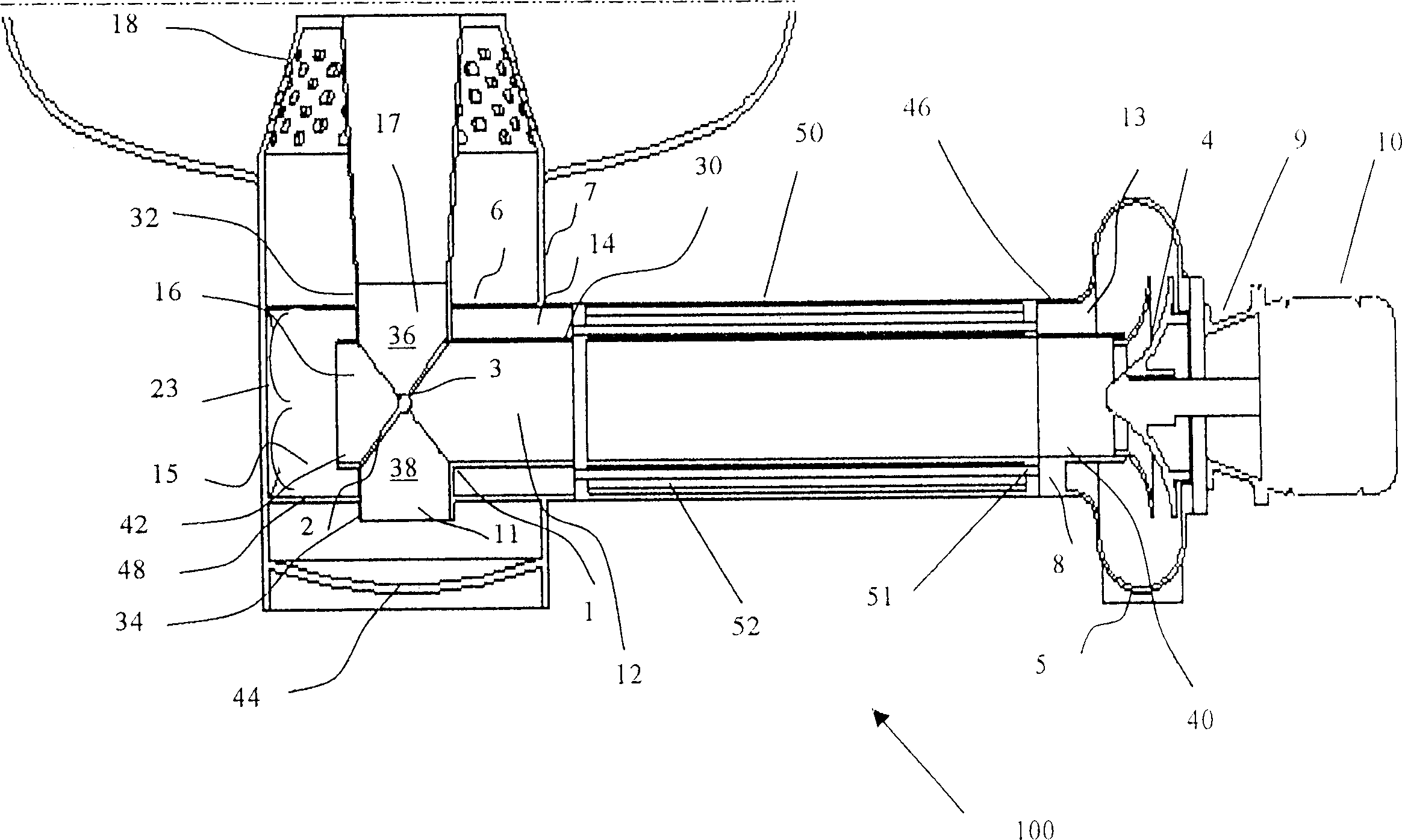
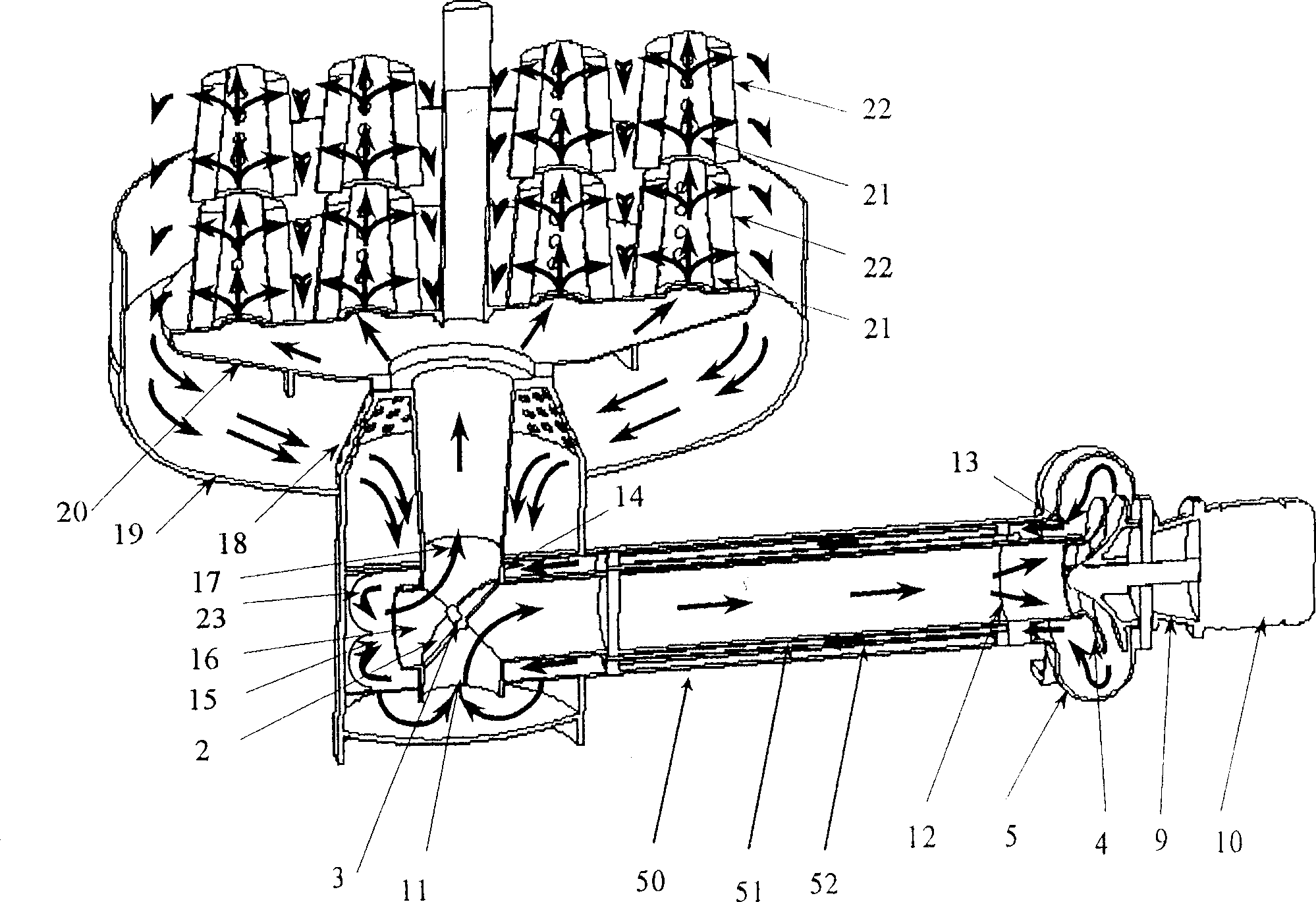
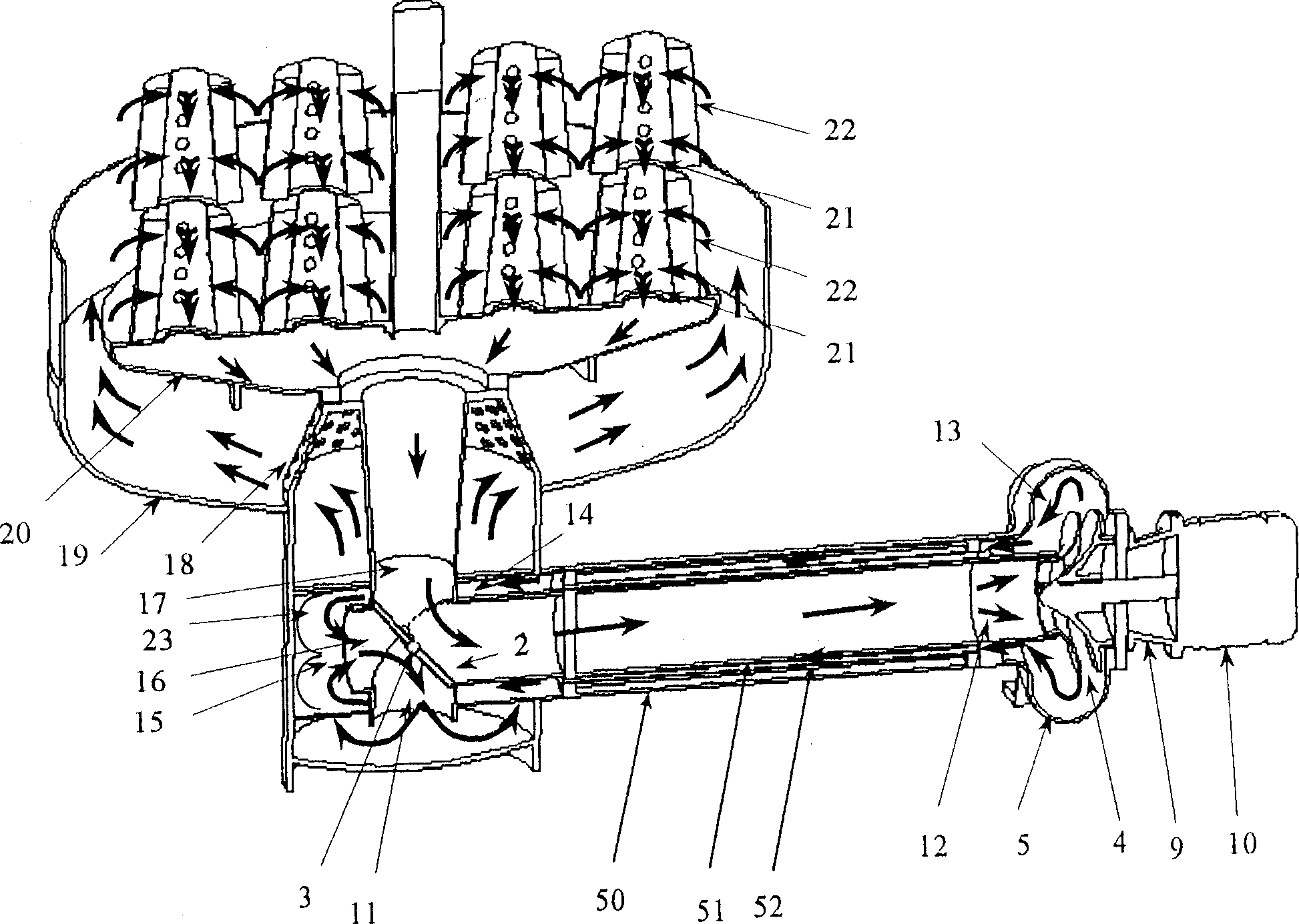
[0054] figure 1 , 2a and 2b show a liquid flow reversing device 100 comprising a cross tube 1 , a rotatable closure member 2 mounted on a shaft 3 , an outer tube 6 and a housing 7 .

[0055] The cross tube 1 comprises a first tube 30 , and first and second tube sections 32 , 34 extending approximately perpendicular to the first tube 30 . The first and second tube sections 32 , 34 extend from opposite sides of the first tube 30 . The first opening 36 and the second opening 38 in the side wall of the first tube 30 ensure that the first tube section 32 and the second tube section 34 respectively communicate with the first tube 30 . The cross pipe 1 has four ports 11 , 12 , 16 and 17 .

[0056] The port 16 of the first tube 30 extends into the interior of the outer tube 6 , so that the cross tube 1 communicates with the outer tube 6 through the port 16 .

[0057] The port 12 of the cross tube 1 is the liquid inlet connected to the centrif...


PUM


Abstract

The present invention provides a fluid flow reversal device (100) comprising a first conduit (1), the first conduit (1) having a cross-shaped configuration provided by a first arm (30) and a second arm (32, 34) thereof, a second conduit (6), which second conduit (6) is concentrically arranged about the first arm (30) of the first conduit (1), the second arm (32, 34) of the first conduit (1) being arranged to extend through opposing sides of the second conduit (6), and a valve (2, 3) designed to control the direction of fluid flow through the second arm (32) of the first conduit (1), in use.

Description

technical field [0001] The present invention relates to a pump, particularly but not limited to a reversible pump. Background technique [0002] Yarn used in textile manufacture is typically wound on a perforated tube or a grooved bobbin to form a permeable enclosure through which dye liquor can circulate during the dyeing process. [0003] During the dyeing process, the permeable package is mounted on a perforated mandrel in a package carrier which is immersed in the dye liquor during the dyeing process. In practice, typically eight or nine packages are stacked on multiple mandrels. A sealing disc was then placed on top of each package cylinder and latched over the mandrel to make the package top watertight. [0004] Encapsulation dyeing treatment involves passing a dye liquor or other treatment fluid through a permeable enclosure. In order to achieve uniform coloring throughout the thickness of the yarn package, the dye liquor is usually passed in two opposite direction...

Claims


Application Information

Patent Timeline
Patent Type & Authority Applications(China)
IPC IPC(8): D06B5/16F16K11/052
CPCF16K11/0525D06B5/16
Inventor 徐达明
Owner FALMER INVESTMENTS LTD
Why Eureka
Try Eureka