
Method of detecting residual oil saturation using single well chemical tracer

A chemical tracer and tracer technology, which is applied in the direction of using chemical indicators for analysis, geophysical measurement, instruments, etc., can solve problems such as unaffordable economy, error in saturation interpretation results, uncertainty about the amount of remaining oil, etc.

Inactive Publication Date: 2003-07-02
PETROCHINA CO LTD
View PDF0 Cites 3 Cited by
  • Summary
  • Abstract
  • Description
  • Claims
  • Application Information

AI Technical Summary

Problems solved by technology

[0003] 1) In the single-well chemical tracer measurement wells, there are oil wells that are not completely flooded. Even if the wells produce a large amount of water, there is still a small amount of mobile oil, so the actual oil saturation of the reservoir is still higher than the real residual oil. The degree of saturation is much larger, and it is theoretically impossible to determine the actual amount of remaining oil using this technology
[0004] 2) This method requires accurate measurement of the tracer slug solution injected into the oil layer and the volume of the push-back fluid produced. Due to the irreversibility of the injection and production process, and the residual fluid volume in the wellbore cannot be calibrated and other factors , it will lead to difficulties in measuring the effective volume of tracer recovery, and there will be errors in the interpretation results of saturation
If high-purity ethyl acetate is used, its cost is 10 times that of ordinary industrial products, and it is economically unaffordable in actual use
Due to the large change in the shape of the tail of the secondary tracer recovery profile, the error of the calculation result is greater than 5% and cannot be used
[0006] 4). This method simplifies the actual tracer slug injection conditions into an ideal pulse (small volume) injection during calculation, ignoring the influence of the size of the tracer slug on the interpretation results, and the actual injection slug The plug is far greater than the condition of the pulse assumption, and the explanation error is greater than 200%. This technology is difficult to be practically applied in the mine

Method used

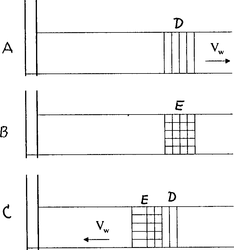
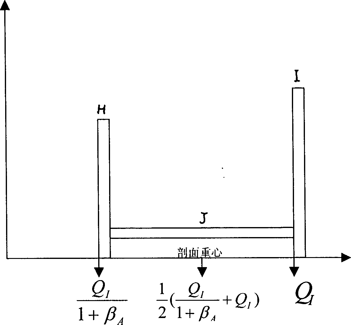
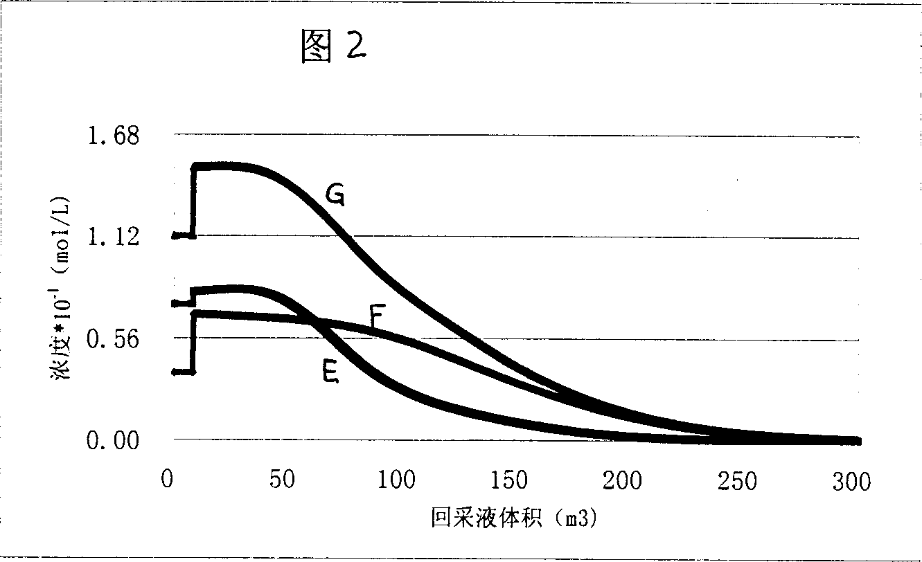

Image

  • Method of detecting residual oil saturation using single well chemical tracer
  • Method of detecting residual oil saturation using single well chemical tracer
  • Method of detecting residual oil saturation using single well chemical tracer

Examples


Embodiment Construction

[0039] Embodiment of the invention

[0040] The present invention adopts single well chemical tracer to measure the method for remaining oil saturation and has following steps:

[0041] 1) Inject the first original tracer slug solution into the oil layer, and at the same time inject the replacement tracer to form the first formation brine solution slug. The first original tracer uses ethyl acetate or propyl acetate or propyl formate , the concentration in brine is 0.1--2.0%. The tracer can use industrial chemical raw materials, which can contain ethanol or propanol, and the replacement tracer can use methanol or butanol;

[0042] 2) Reinject the second original tracer of chemical ester different from the chemical composition of the tracer used in the first slug to form the second saline solution slug. For example, ethyl acetate is used for the first original tracer, and ethyl acetate is used for the second The original tracer uses propyl acetate or propyl formate, and vice ve...


PUM


Abstract

A method for measuring the saturability of residual petroleum with single oil well chemical tracer includes such steps as injecting the first original tracer as segment blocking solution in oil bearing stratum, injecting methanol or butanol to displace tracer to form the segment blocking of stratum salt's aqueous solution, injecting the second original tracer to form the second segment blocking, driving the first segment blocking to the oil bearing stratum far from oil well, closing the well and stop flowing, recovering oil, recording the relation curve between the concentration of tracer and output liquid scaling the stay volume in well, scaling the effective injected volumes for both injection, finding the recovering cross-section of the first tracer, and calculating the saturability of residual oil.

Description

technical field [0001] The invention relates to well logging technology in oil exploitation, in particular to a method for measuring remaining oil saturation by using a single well chemical tracer. Background technique [0002] Americans Deans and Tomich proposed the single-well chemical tracer method to measure residual oil saturation in 1971. This technology skillfully utilizes the movement time difference between the tracer and its reactants in the oil layer to determine the water-flooded well. Residual oil saturation of nearby oil reservoirs. The specific method is to first inject a slug of formation brine containing chemical tracers (such as ethyl acetate) into the oil layer, and then inject brine without tracers, and drive the brine slug containing chemical tracers to formations far away from the wellbore In the process, when the depth to be tested is reached (generally 7-12 meters), then the well is shut down and the flow is stopped for a period of time. During well...

Claims


Application Information

Patent Timeline
IPC IPC(8): G01N31/22G01V9/00
Inventor 裴连君王仲林燕列灿
Owner PETROCHINA CO LTD
Learn More