

Disk type motor
A disk-shaped and rotor technology, applied in the field of disk-shaped motors, can solve the problems of inability to utilize the excitation force of the stator, large self-excited magnetism, and high manufacturing costs, and achieve the goal of improving power saving effects, improving heat resistance, and reducing material costs Effect
- Summary
- Abstract
- Description
- Claims
- Application Information
AI Technical Summary
Problems solved by technology
Method used
Image

Examples
Embodiment Construction
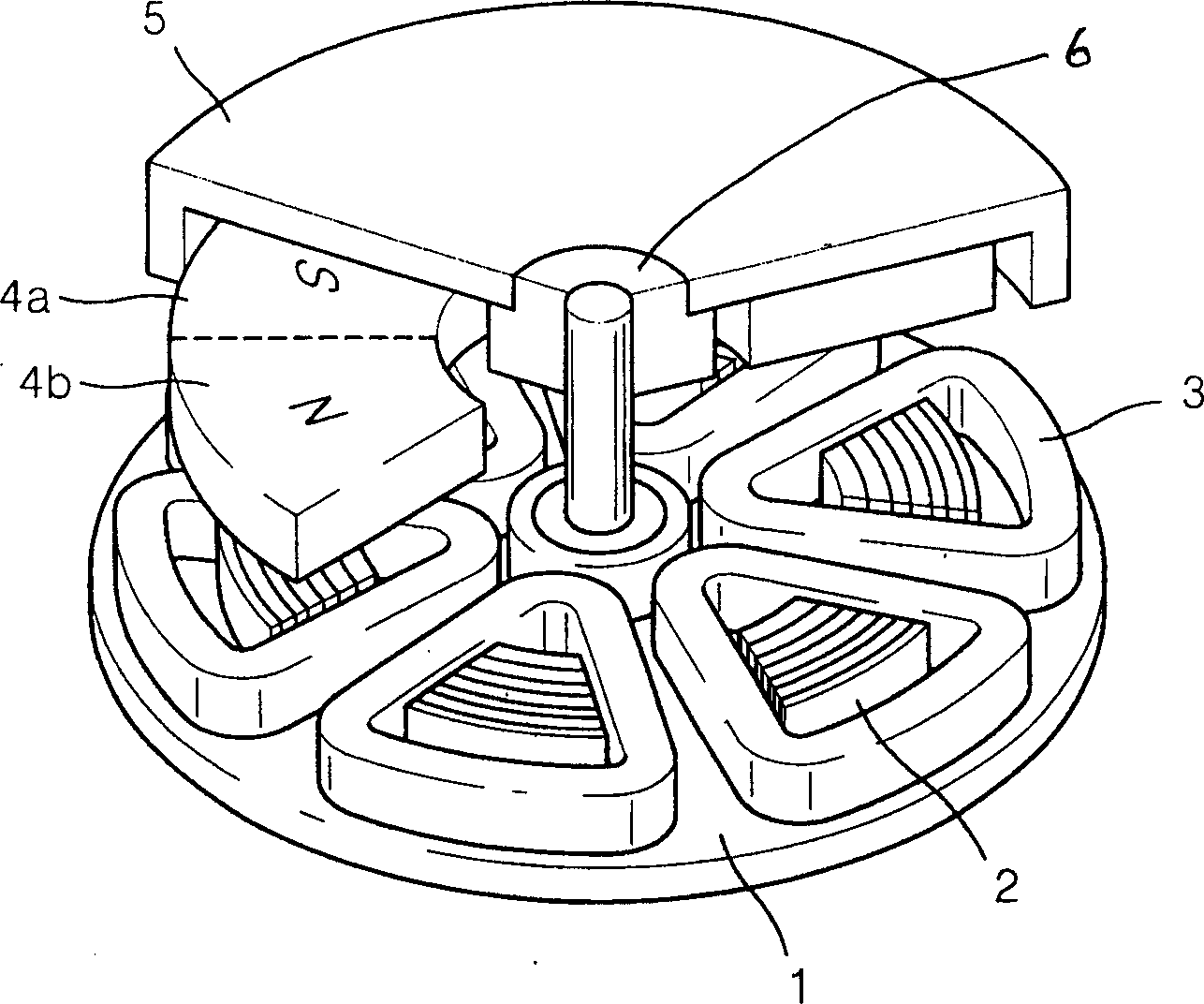
[0025] The disk motor of the present invention will be described below with reference to the drawings.
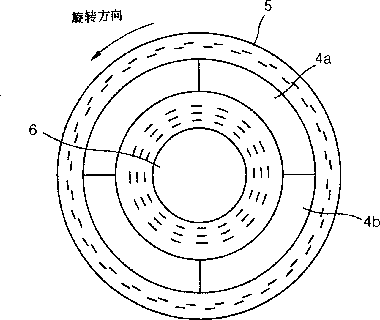
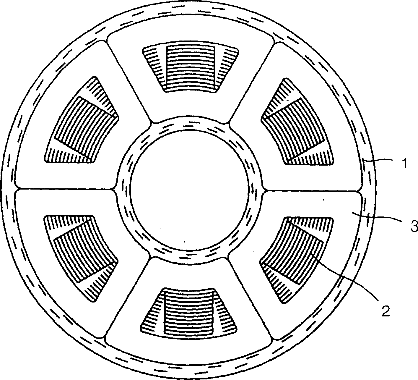
[0026] Such as Figure 4a As shown, the disc motor of the present invention comprises a salient pole iron core 2 with a certain length in the direction of the drive shaft, and a stator 1 that is wound with a winding 3 on the iron core 2 and plays an electromagnetic role, and is perpendicular to the center of the stator 1. Shaft 6 is provided, located in the facing direction of the stator 1, and has a certain distance to form at least one pair of permanent magnets for S pole 4a and N pole 4b excitation; a circular rotor 18 of salient pole iron 17 is installed between the permanent magnets, The shaft 6 etc. which transmit the rotational force of the said rotor 18 to a load are comprised.
[0027] Such as Figure 4b As shown, the rotor 18 of the disk motor of the present invention is centered on the shaft 6, forming a plurality of permanent magnets excited by S poles 16a and...
PUM
 Abstract
Description
Claims
Application Information