System for sealing off gap

A technology of gaps and sealing strips, applied in the structural field of steam turbines, to achieve the effect of improving thermal shock resistance and sealing ability

Inactive Publication Date: 2003-07-02
SIEMENS AG
View PDF1 Cites 12 Cited by
  • Summary
  • Abstract
  • Description
  • Claims
  • Application Information

AI Technical Summary

Problems solved by technology

[0006] However, in the known labyrinth seals and in the construction according to US Pat. next to contact
On the other hand, apart from the occasional moment of contact between the elements, the result of the above-mentioned sealing is that there is a gap in which a part of the working medium flows through the turbine blades without being utilized, and this part of the working medium should not be ignored

Method used


Image

  • System for sealing off gap
  • System for sealing off gap
  • System for sealing off gap

Examples


Embodiment Construction

[0021] In all figures, parts that are identical to each other are provided with the same reference numerals.

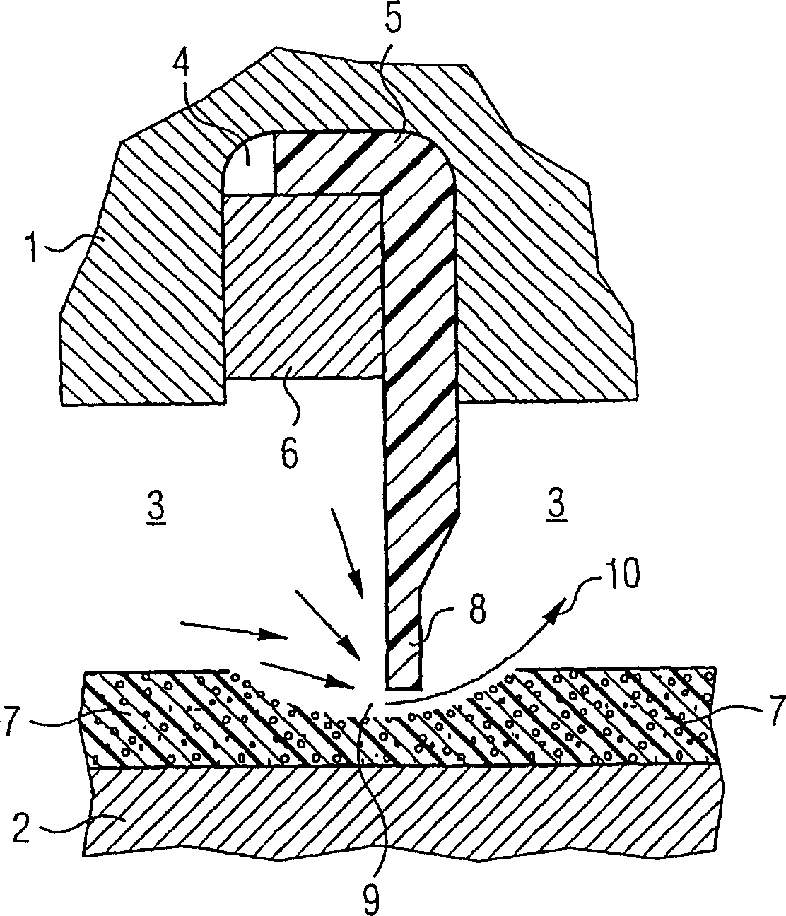
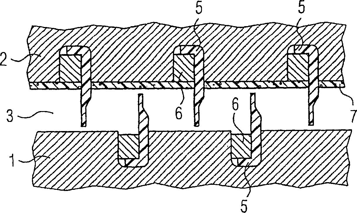
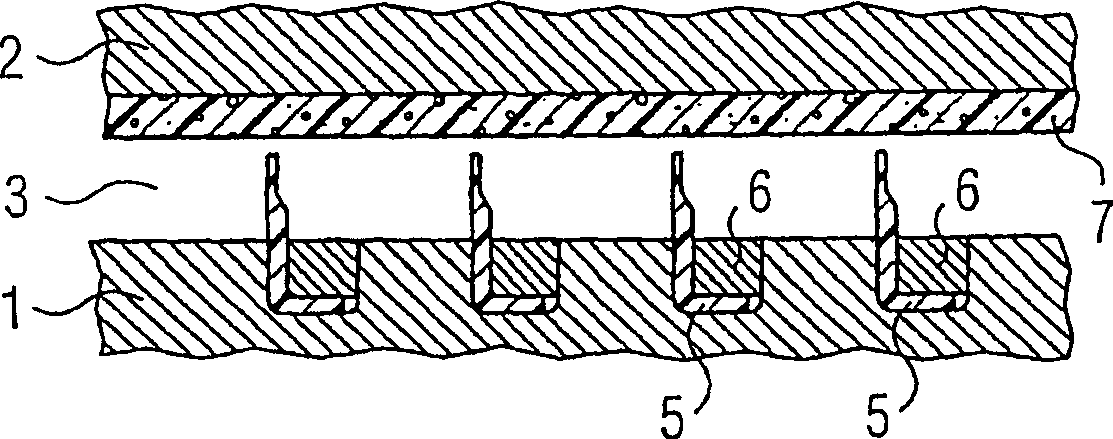
[0022] exist figure 1 In this case, elements 1 and 2 of a steam turbine (not shown in detail) form a gap a few millimeters wide which is sealed against the steam flow. The element 1 is preferably a rotor part that rotates in the operating state and has a groove 4 for receiving a sealing strip 4 as a sealing lip, the cross-sectional shape of the sealing strip 5 is "L"-shaped and its section is shorter The legs rest on the bottom of the groove 4 . The sealing strip 5 consists of one or more parts complementary to each other in the circumferential direction to form a ring and is fixed in the groove 4 by a calking wire 6 .

[0023] The element 2 on the other side of the gap 3 relative to the element 1 is preferably stationary during operation and has a coating designed as a contact layer 7 . The coating has a thickness of 0.5 to 0.1 times the width of the gap 3, is mad...


PUM


Abstract

In fluid machines frequently gaps between movable (1) and stationary (2) structural parts have be sealed off. Frequently so-called labyrinth packings are used, whereby sealing strips (5) brush against the opposite structural part. The aim of the invention is to provide an improved system. To this end, a brush layer (7) is configured as a porous coating that can be detached from the opposite structural part (1,2). The inventive system can be advantageously used in virtually any fluid machines.

Description

technical field [0001] The invention relates to a structure for a fluid flow machine, especially a steam turbine, for sealing a gap between a movable element and a stationary element, the structure carrying a grazing layer on the surface flanking the gap. Background technique [0002] In machines that manipulate and process flowing liquid and / or gaseous media, gaps between movable and stationary elements often need to be sealed against the flowing media. Such seals are particularly useful in turbines containing steam, where the gap between the rotor and the casing surrounding the rotor is sealed so that the passage of steam through the blade ring is blocked. The quality of these seals has a great influence on the efficiency of these machines, especially in the case of steam turbines. [0003] To achieve this, axially arranged sealing strips next to each other are used in the construction of the steam turbine, which are also referred to as labyrinth seals. These seals are c...

Claims


Application Information

Patent Timeline
Patent Type & Authority Applications(China)
IPC IPC(8): F01D11/02F01D11/12F16J15/447
CPCF01D11/02F01D11/122
Inventor 卡伊·维格哈特
Owner SIEMENS AG
Why Eureka
Try Eureka