Printing method and printing device for non-individual body sheet

A printing method and continuum technology, used in printing, printing presses, rotary printing presses, etc., and can solve problems such as wrinkling, sheet undercut, deformation, etc.

Inactive Publication Date: 2003-07-16
MURATA MFG CO LTD
View PDF1 Cites 16 Cited by
  • Summary
  • Abstract
  • Description
  • Claims
  • Application Information

AI Technical Summary

Problems solved by technology

[0009] However, the raw material sheet to be printed is made thinner and thinner for small size and large capacity. If the printing table is moved in the X, Y, and θ directions for the alignment of the continuum sheet, the extremely thin raw material sheet will be subjected to excessive tension. Tensile stress, which becomes the cause of wrinkling or deformation
As a result, there are problems such as chipping, deterioration of conveying accuracy, etc.

Method used


Image

  • Printing method and printing device for non-individual body sheet
  • Printing method and printing device for non-individual body sheet
  • Printing method and printing device for non-individual body sheet

Examples


no. 1 Embodiment

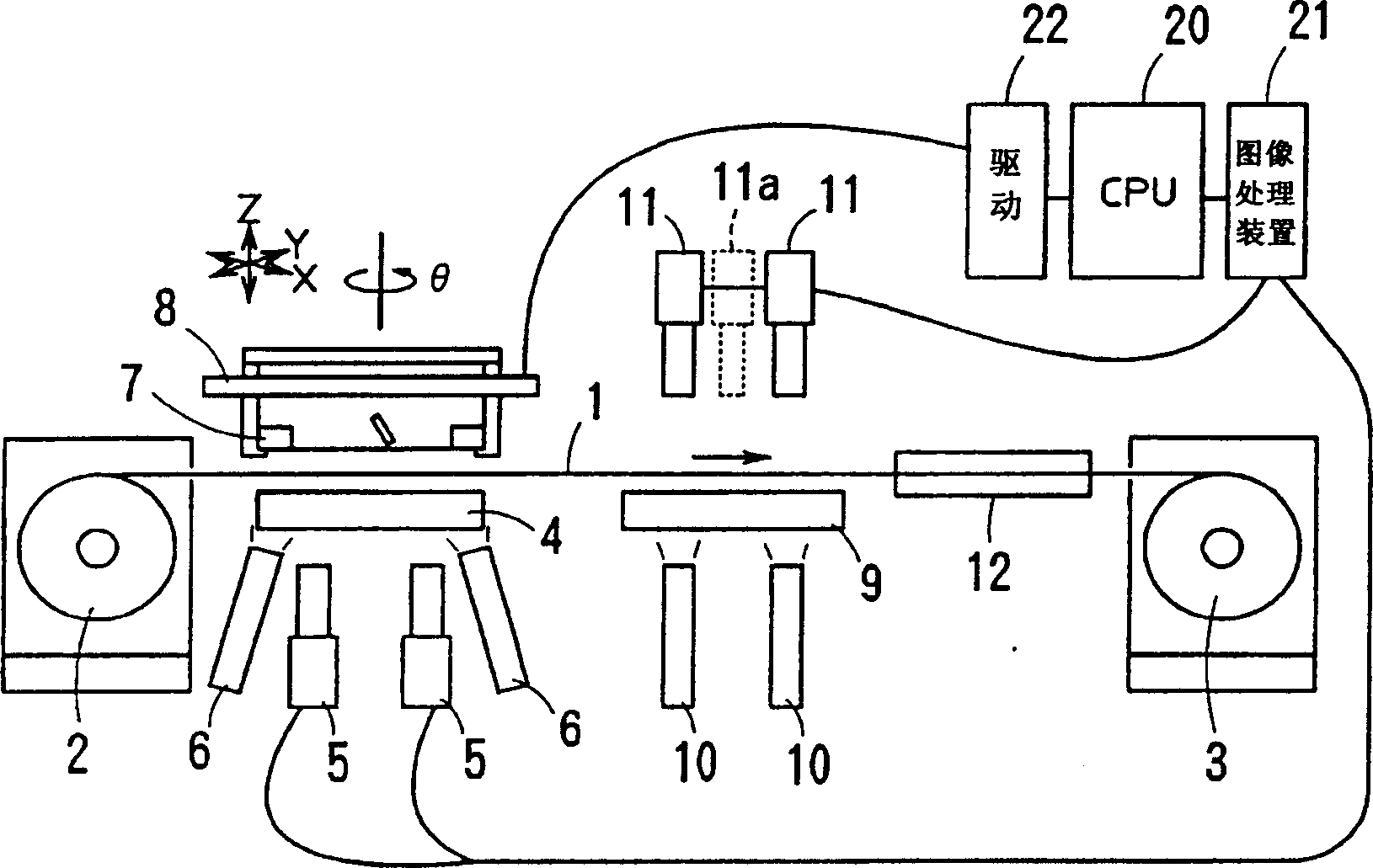
[0061] figure 1 An example of a continuous sheet printing device related to the present invention is shown.

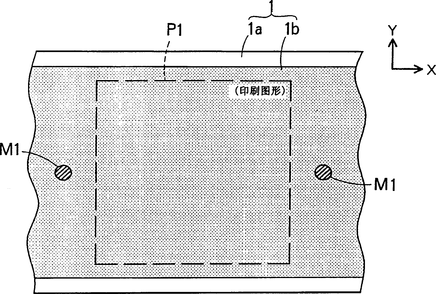
[0062] The continuum sheets used here 11 and figure 2 The raw material ceramic layer 1b is formed in a continuous film form on a flexible support body 1a such as a relatively long carrier film as shown, and the first pattern P1 and the pattern corresponding to the P1 are formed in advance by printing or the like at certain intervals in the longitudinal direction on the upper surface thereof. Multiple alignment marks M1. In this example, the pattern P1 and the mark M1 are printed to a predetermined thickness using an electrode material such as Ni paste. When the thickness of the ceramic layer 1b is 5 μm-0.2 μm, because the continuum sheet 1 itself is almost transparent, so the back side of the continuum sheet 1 can be seen through, and the pattern P1 and the mark M1 can be recognized, as will be described later. Logo M2 for printing plate 7. The alignment mark M1 ...

no. 2 Embodiment

[0080] The amount of printing deformation in screen printing can be known from the large deviation of each pattern. Such as Figure 10 Shown: When the marks M1 and M2 for position deviation detection are arranged outside the surroundings of the patterns P1 and P2', the marks M1 and M2 can be aligned, but the patterns P1 and P2' do not have to be aligned.

[0081] Figure 10 (a) is when the mutual positional relationship between the sign M1 and the pattern P1, the sign M2 and the pattern P2' is equal, Figure 10 (b) is when the mutual positional relationship is different.

[0082] However, by using the feedback correction value (B'-A) ​​obtained by image processing and the correction value of both sides of the offset (offset) value calculated by measuring the mutual position of the printed coating film in advance, so that the original desired pattern P1, The position offset correction of P2' is corrected together with other offsets due to long-term differences. In order to ...

no. 3 Embodiment

[0087] In the first and second embodiments, after printing at the printing station 4, the printing offset at the feedback station 9 is obtained and fed back, but in the third embodiment, the feedback station is omitted, and the printing offset is obtained at the printing station 4 Feedback for the next printing.

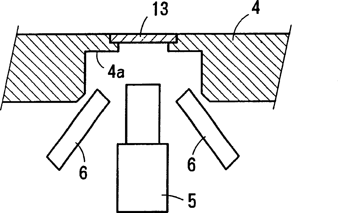
[0088] Although the system diagram of the printing device of the third embodiment is omitted, it is from figure 1 In the printing unit shown, the system of feedback table 9, lighting 10, camera 11, etc. has been omitted. In addition, the amount of displacement between the printed position identification mark M2 and the alignment mark M1 is measured by image processing with the camera 5 provided on the printing table 4 .

[0089] Figure 13 , Figure 14 It is a flowchart of the printing method of the third embodiment.

[0090] exist Figure 13 In the initial printing shown, the processing of steps S1 to S7 is the same as Figure 7 . After printing, the continu...


PUM


Abstract

The invention provides a method for printing a continuous body sheet by which the position of the sheet can be registered highly precisely without applying an excess tensile stress to the sheet, and a printer. This method comprises a step to prepare a printing plate arranged above a printing stage, a step to retain the continuous body sheet on the printing stage by suction, a step to screen-print a specified pattern on the suction-retained continuous body sheet by the printing plate and at the same time, screen-print a position discerning mark of the printing plate on the sheet, a step to convey the sheet to a feedback stage from the printing stage and retain the sheet by suction, a step to seek a deviation level between each of the position registering marks of the sheet retained on the feedback stage by suction and each of the printed position discerning marks of the printing plate by image processing and a step to control the positions of the printing plate in a feedback mode according to the sought deviation level.

Description

technical field [0001] The invention relates to a printing method and a printing device for performing screen printing on a continuous sheet with a plurality of alignment marks set in advance. technical background [0002] Conventionally, as a device for manufacturing ceramic green sheets for laminated electronic components, it is known that a raw ceramic layer is formed on a carrier film having a relatively long length, and the continuum sheet is sequentially kept in a continuous state. A device for obtaining a ceramic raw material sheet through a plurality of processes such as an electrode film printing process, a drying process, and a blanking process (refer to Japanese Patent No. 2504277). [0003] In recent years, the raw ceramic layer has been made very thin below 10 μm, and if an electrode film is printed on it, a height difference of the electrode film will occur. When such raw ceramic layers are laminated, problems such as cracks and delamination may occur due to t...

Claims


Application Information

Patent Timeline
Patent Type & Authority Applications(China)
IPC IPC(8): B41F15/36B41F15/08B41F15/20B41F15/24B41F15/26B41F15/28H05K3/12
Inventor 早川和久林一知西村孝士
Owner MURATA MFG CO LTD
Why Eureka
Try Eureka