Carburetor

A vaporizer and container technology, applied in the field of liquefied petroleum gas vaporization devices, can solve the problems of poor thermal efficiency and the like

Inactive Publication Date: 2003-08-06
ITO CO LTD
View PDF0 Cites 3 Cited by
  • Summary
  • Abstract
  • Description
  • Claims
  • Application Information

AI Technical Summary

Problems solved by technology

[0005] As mentioned above, heater 12 is arranged at the bottom of warm water tank 11 in the vaporizer of formation, owing to be provided with helical tube 13 (evaporator) thereon, the inte...

Method used


Image

  • Carburetor
  • Carburetor
  • Carburetor

Examples


Embodiment Construction

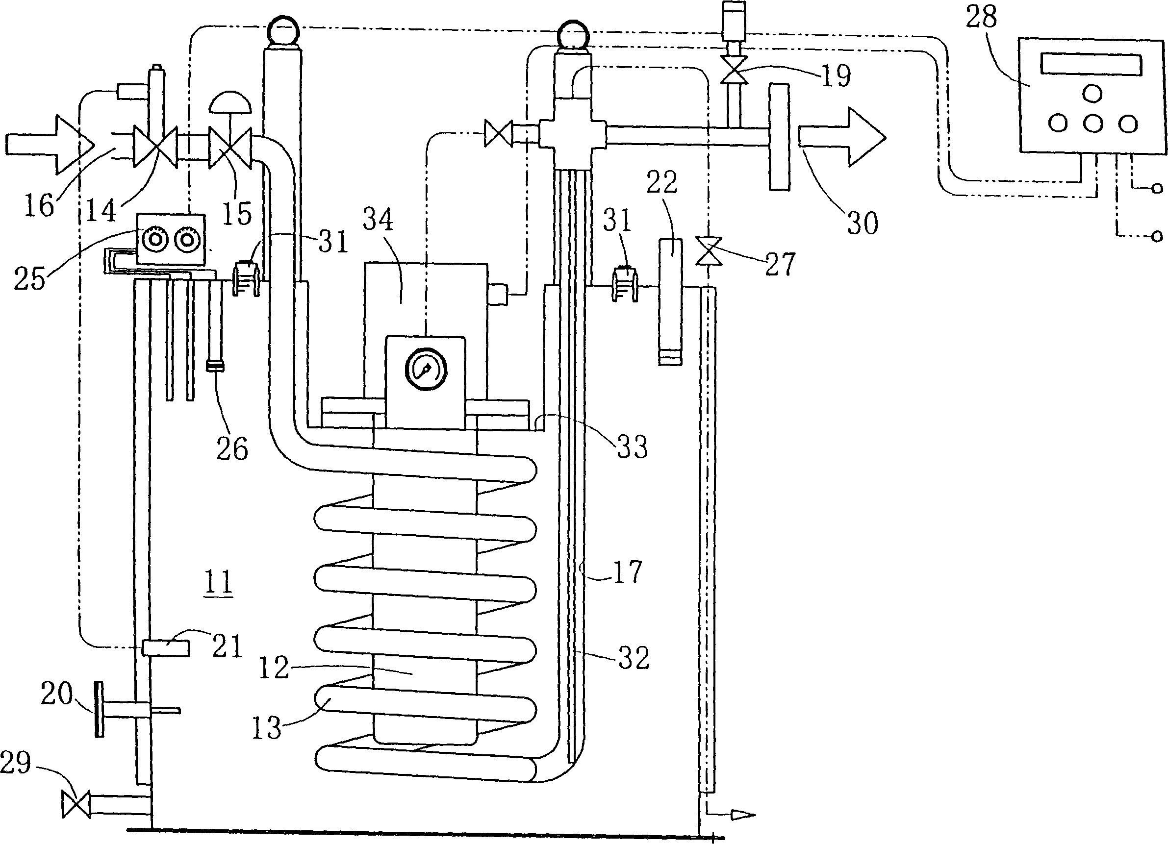
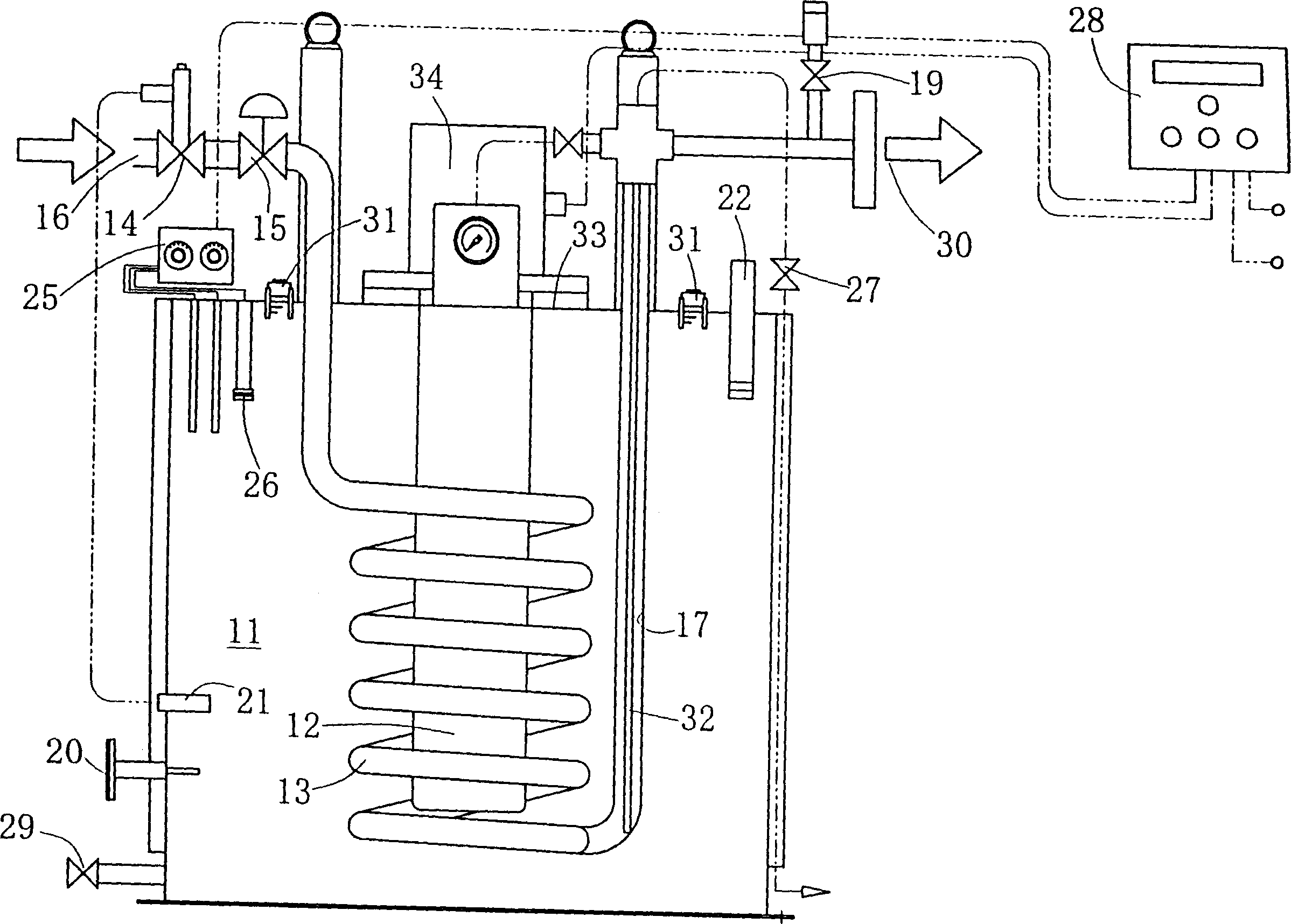
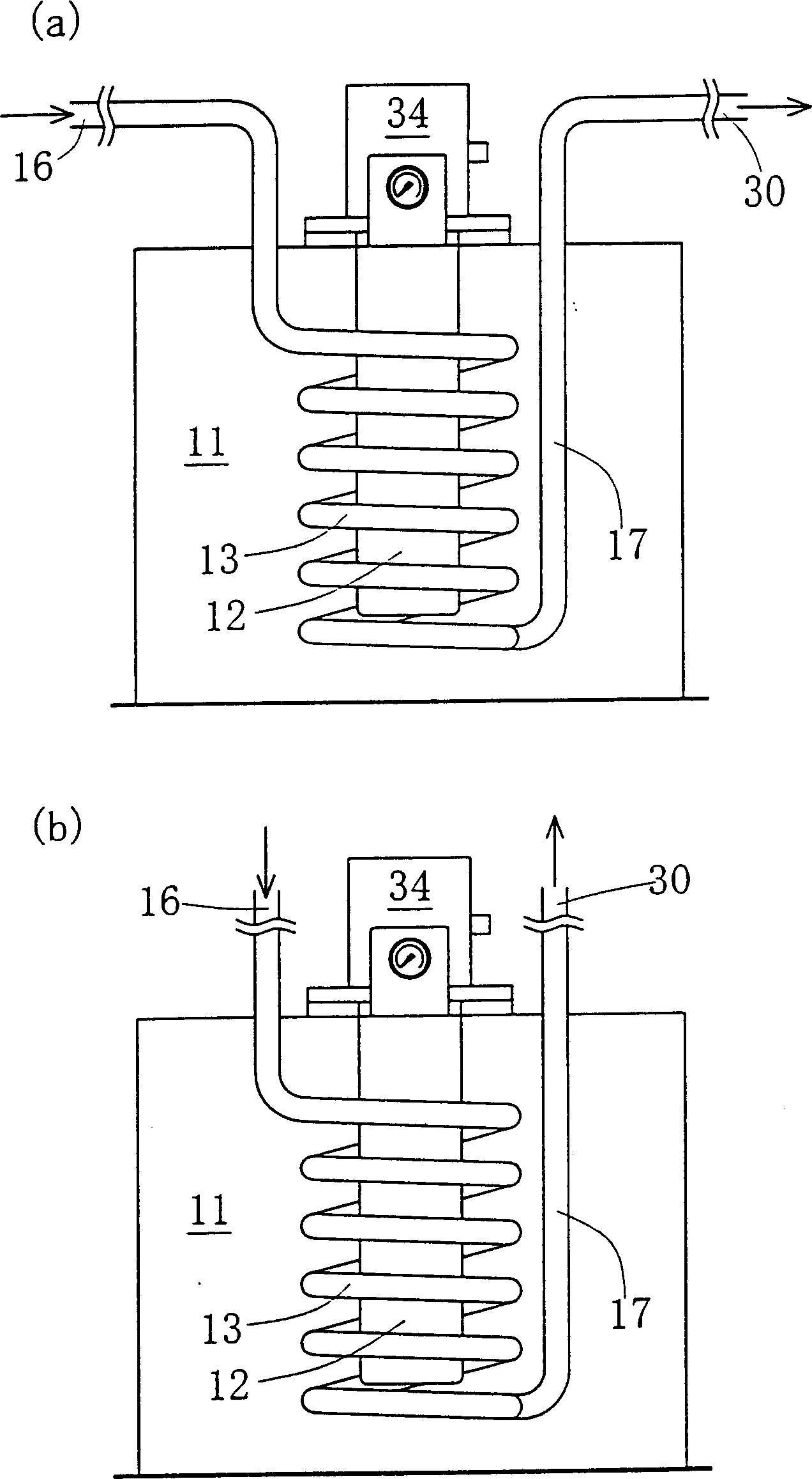
[0040] Embodiments of the present invention will be described below with reference to the drawings. The LPG imported from the air storage tank passes through the introduction pipe 16, the liquid overflow protection valve 14, and the hydraulic adjustment valve 15 to the warm water tank 11, and then continuously turns into a spiral tube 13, which is connected to the evaporation cylinder 17 near the bottom of the warm water tank 11 and passed through the extension tube. The upwardly facing safety valve 19 is connected to a consumption line 30 .

[0041] On the other hand, the heater 12 is arranged at the center of the spiral tube 13 at equal intervals from the surrounding spiral tubes 13 .

[0042] The warm water tank 11 is equipped with a thermometer 20 for warm water, a temperature sensor 21 for actuating the liquid overflow protection valve, a temperature regulator 25, a float switch 26, a gas discharge valve 31 for the warm water tank, a water level gauge 22, and a thin tube ...


PUM


Abstract

The present invention relates to a vaporizer for improving thermal efficiency by miniaturizing a hot water tank by improving arrangement of a spiral pipe and a heater. A liquefied petroleum gas vaporizer has the hot water tank 11 for controlling heating of a heating medium housed in a vessel by the heater 12, and a heat exchange pipe arranged so as to sink in the heating medium of this hot water tank 11, and connects the upstream side of the heat exchange pipe to a liquefied petroleum gas introducing pipe 16 via a fluid pressure regulating valve 15 and a liquid outflow preventive valve 14, and connects the downstream side to a gas consuming pipe 30. The heat exchange pipe is formed of a spiral pipe 13. The heater 12 is arranged in the center of the spiral pipe 13. The spiral pipe 13 and the heater 12 are vertically arranged.

Description

[0001] [Technical field of invention] [0002] The present invention relates to a liquefied petroleum gas (hereinafter referred to as LPG) vaporizer capable of improving vaporization efficiency and reducing installation space. [Background technique] [0003] like Figure 4 As shown, the LPG vaporizer is provided with a heater 12 at the bottom of the warm water tank 11, and the warm water tank 11 is provided with a spiral pipe 13 (evaporator), and the LPG is introduced into This helical tube 13 is vaporized. [0004] In the figure, 16 is the LPG inlet pipe, 17 is the evaporation cylinder, 18 is the main valve of the secondary pressure gauge, 19 is the safety valve, 20 is the thermometer of the warm water tank, 21 is the temperature sensor of the liquid overflow protection valve, and 22 is the water level Meter, 23 is a primary pressure gauge, 24 is a secondary pressure gauge, 25 is a temperature regulator for a warm water tank, 26 is a float switch, 27 is a discharge valve of ...

Claims


Application Information

Patent Timeline
IPC IPC(8): F17C7/04F23K5/22F28D7/02
CPCF17C7/04F17C2205/0323F17C2205/0352F17C2205/0382F23K5/22F28D7/02
Inventor 桥本义文
Owner ITO CO LTD
Why Eureka
Try Eureka