

Prepn of porous luminescent material
A technology of porous silicon and ultrasonic generator, which is applied in the field of preparation of porous silicon materials by electrochemical anodic corrosion method, can solve the problems of slow chemical reaction, difficulty, and increase in resistance of silicon wafers, etc., and achieve simple and convenient process, good optical characteristics, and products good performance
Inactive Publication Date: 2003-08-20
FUDAN UNIV
View PDF0 Cites 8 Cited by
- Summary
- Abstract
- Description
- Claims
- Application Information
AI Technical Summary
Problems solved by technology
When the traditional DC etching method is used to etch porous silicon, the silicon-fluorine compound produced is easy to deposit at the bottom of the hole, and the H 2 Bubbles are adsorbed on the surface of the silicon column due to surface tension, which hinders the penetration of the etching solution into the bottom of the silicon hole, making the chemical reaction slow and difficult
On the other hand, the reaction deposits cause the resistance of the silicon wafer to increase and the reaction current density to decrease, which is not conducive to maintaining a certain reaction speed.
Method used
View moreImage
Smart ImageViewing Examples

Examples
Embodiment Construction
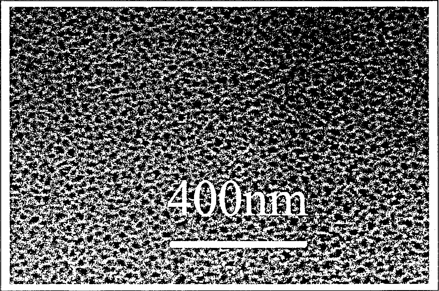
[0015] Put the existing pulse current corrosion tank into the ultrasonic generator, put a certain amount of water in the ultrasonic generator, and turn on the ultrasonic generator while performing pulse current corrosion. The ultrasonic is 33KHZ. Since the silicon wafer is thin, ultrasonic corrosion is selected. The time is 5 minutes. The result is as figure 2 .
[0016] According to the thickness of different silicon wafers, the frequency is 25KHZ, 30KHZ, 180KHZ, and the time is 5 seconds, 1 hour, 5 hours for ultrasonic etching, and the samples with significantly improved surface interface structure and optical properties are prepared.
Login to View More PUM
 Abstract
The present invention is supersonic electrochemical etching process of preparing porous luminescent silicon material. The traditional porous silicon material preparing electrochemical processes, including DC current process and pulse current process, has some demerits resulting in porous silicon material with imperfect optical characteristics. The supersonic electrochemical etching process of the present invention has optimized etching condition, and can obtain porous silicon material with improved surface interface structure and optical characteristics.
Description
technical field [0001] The invention is a new method for preparing porous silicon material by electrochemical anode corrosion method. Background technique [0002] Porous silicon, that is, a porous silicon material, was originally used as a structural isolation layer in integrated circuits, because the holes in the silicon pillars in the porous silicon layer are depleted and have a large resistance. Porous silicon didn't attract much attention at the time. From the first reported discovery of porous silicon in the 1950s and the nearly 40 years thereafter, there have been less than 200 related articles. In 1990, British scientist L. T. Canham discovered the high-efficiency emission of visible light from porous silicon at room temperature, which opened up a new field for all-silicon-based optoelectronic integration, and soon caused a research boom in the scientific community. People have not only carried out theoretical and experimental studies on the basic characteristics o...
Claims
Login to View More Application Information
Patent Timeline
 IPC IPC(8): C25F3/12
Inventor侯晓远柳毅熊祖洪徐少辉柳玥刘小兵丁训民
OwnerFUDAN UNIV