Supercharge Your Innovation With Domain-Expert AI Agents!

Optical waveguide diffraction grating device, method for fabricating thereof, multiplexing/demultiflexing module, and optical transmission system

A diffraction grating and optical waveguide technology, applied in the field of optical transmission systems, can solve problems such as energy loss and high incidence of receiving errors

Inactive Publication Date: 2003-09-10
SUMITOMO ELECTRIC IND LTD
View PDF0 Cites 3 Cited by
  • Summary
  • Abstract
  • Description
  • Claims
  • Application Information

AI Technical Summary

Problems solved by technology

[0007] Therefore, if a multiplexer / demultiplexer including such an optical waveguide type diffraction grating element is used in a WDM transmission system, the light of the wavelength that should be transmitted actually passes through the light of the optical waveguide type diffraction grating element and although It is the light of the wavelength that should be reflected, but a part of the light that has passed through the optical waveguide type diffraction grating element. When the difference between each wavelength is small, cross-light will occur and the incidence of reception errors will increase.
In addition, since part of the light of the wavelength that should be reflected passes through the optical waveguide type diffraction grating element, the part of the light that is the wavelength that should be reflected is actually reflected by the optical waveguide type diffraction grating element will cause energy loss.
Similarly, because part of the light of the wavelength that should be transmitted is reflected by the optical waveguide type diffraction grating element, the part of the light that should be transmitted by the optical waveguide type diffraction grating element will also generate energy loss in practice.

Method used


Image

  • Optical waveguide diffraction grating device, method for fabricating thereof, multiplexing/demultiflexing module, and optical transmission system
  • Optical waveguide diffraction grating device, method for fabricating thereof, multiplexing/demultiflexing module, and optical transmission system
  • Optical waveguide diffraction grating device, method for fabricating thereof, multiplexing/demultiflexing module, and optical transmission system

Examples


Embodiment Construction

[0032] Hereinafter, embodiments of the present invention will be described in detail with reference to the drawings. Here, in the description of the drawings, the same reference numerals are attached to the same elements, and overlapping descriptions are omitted.

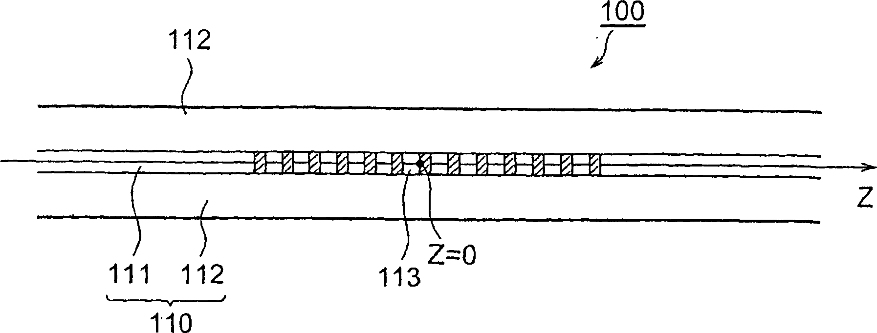
[0033] First, an embodiment of the optical waveguide type diffraction grating element and its manufacturing method according to the present invention will be described. figure 1 It is an explanatory diagram of the optical waveguide type diffraction grating element 100 according to the present invention. This figure shows a cross-sectional view of the optical waveguide type diffraction grating element 100 when the plane including the optical axis is cut. This optical waveguide type diffraction grating element 100 is an element in which a diffraction grating 113 is formed on an optical fiber 110 serving as an optical waveguide. The optical fiber 110 is an optical fiber mainly composed of silica glass, and GeO is dop...


PUM

PropertyMeasurementUnit
Reflectivityaaaaaaaaaa

Abstract

An optical waveguide diffraction grating device in which a diffraction grating by diffractive index modulation is provided over a predetermined length in the direction of propagation of light along an optical waveguide and the light in a reflection band out of the light propagated through the optical waveguide is selectively reflected by the diffraction grating. The reflection band is divided into K (K = 2) wavelength bands. The refractive index modulation DELTA nall within the predetermined length is the sum of the refractive index modulations DELTA nk (k=1 to K) of the periods LAMBDA k corresponding to the K wavelength bands. At least a pair of phases out of the phases PHI k (k=1 to K) of the diffractive index modulation DELTA nk at the central position of the predetermined length are different from each other. In such way, an optical waveguide diffraction grating device which is short as a whole, is manufactured at low cost, and has excellent reflection / transmission characteristics is provided.

Description

technical field [0001] The present invention relates to an optical waveguide type diffraction grating element in which a diffraction grating utilizing refractive index modulation is formed over a predetermined range of an optical waveguide direction in an optical waveguide, a manufacturing method thereof, and light multiplexing or light combining including the optical waveguide type diffraction grating element. A multiplexer / demultiplexer component for demultiplexing, and an optical transmission system including the multiplexer / demultiplexer component using multi-wavelength signal light for optical transmission. Background technique [0002] The optical waveguide type diffraction grating element is an optical waveguide type diffraction grating element in which a diffraction grating utilizing refractive index modulation is formed over a predetermined range of an optical waveguide direction in an optical waveguide (such as an optical fiber), and with the diffraction grating, it...

Claims


Application Information

Patent Timeline
IPC IPC(8): G02B6/12G02B6/02G02B6/34
CPCG02B6/29353G02B6/2932G02B6/02085G02B6/29334G02B6/2938G02B6/02138G02B6/02
Inventor 柴田俊和菅沼宽井上享塩崎学
Owner SUMITOMO ELECTRIC IND LTD
Features
  • R&D
  • Intellectual Property
  • Life Sciences
  • Materials
  • Tech Scout
  • Unparalleled Data Quality
  • Higher Quality Content
  • 60% Fewer Hallucinations
Learn More