

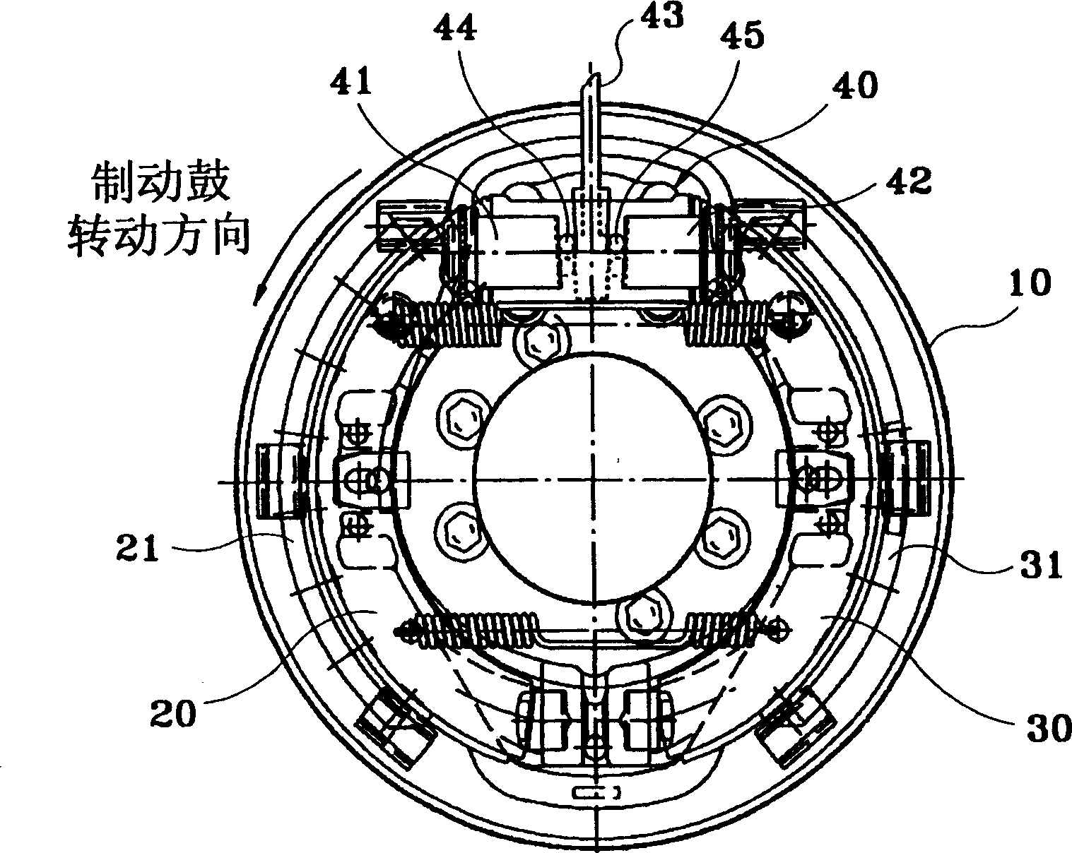
Wedge actuating drum type brake
A drum brake and actuation technology, applied in the direction of hydraulic drum brake, drum brake, brake type, etc., can solve the troublesome task of disassembling the hub and brake drum assembly, uneven wear of the lining, and the inability of the piston 42 full use of
- Summary
- Abstract
- Description
- Claims
- Application Information
AI Technical Summary
Problems solved by technology
Method used
Image

Examples
Embodiment Construction
[0020] Such as image 3 As shown, when forming the two slopes 41 and 42 of the support wedge 43 , the inclination angle on the side of the trailing shoe 30 is larger than that on the side of the leading shoe 20 .
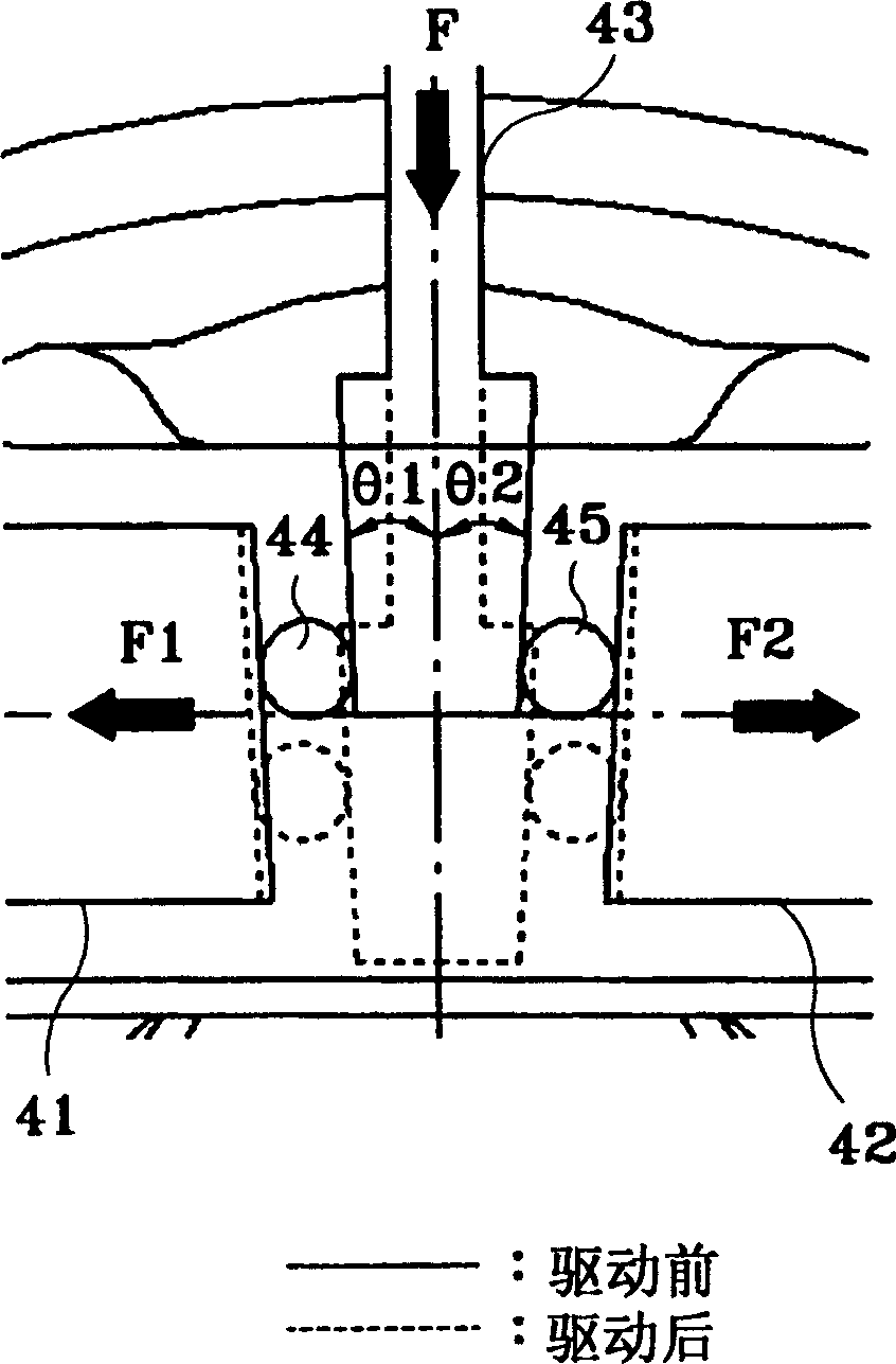
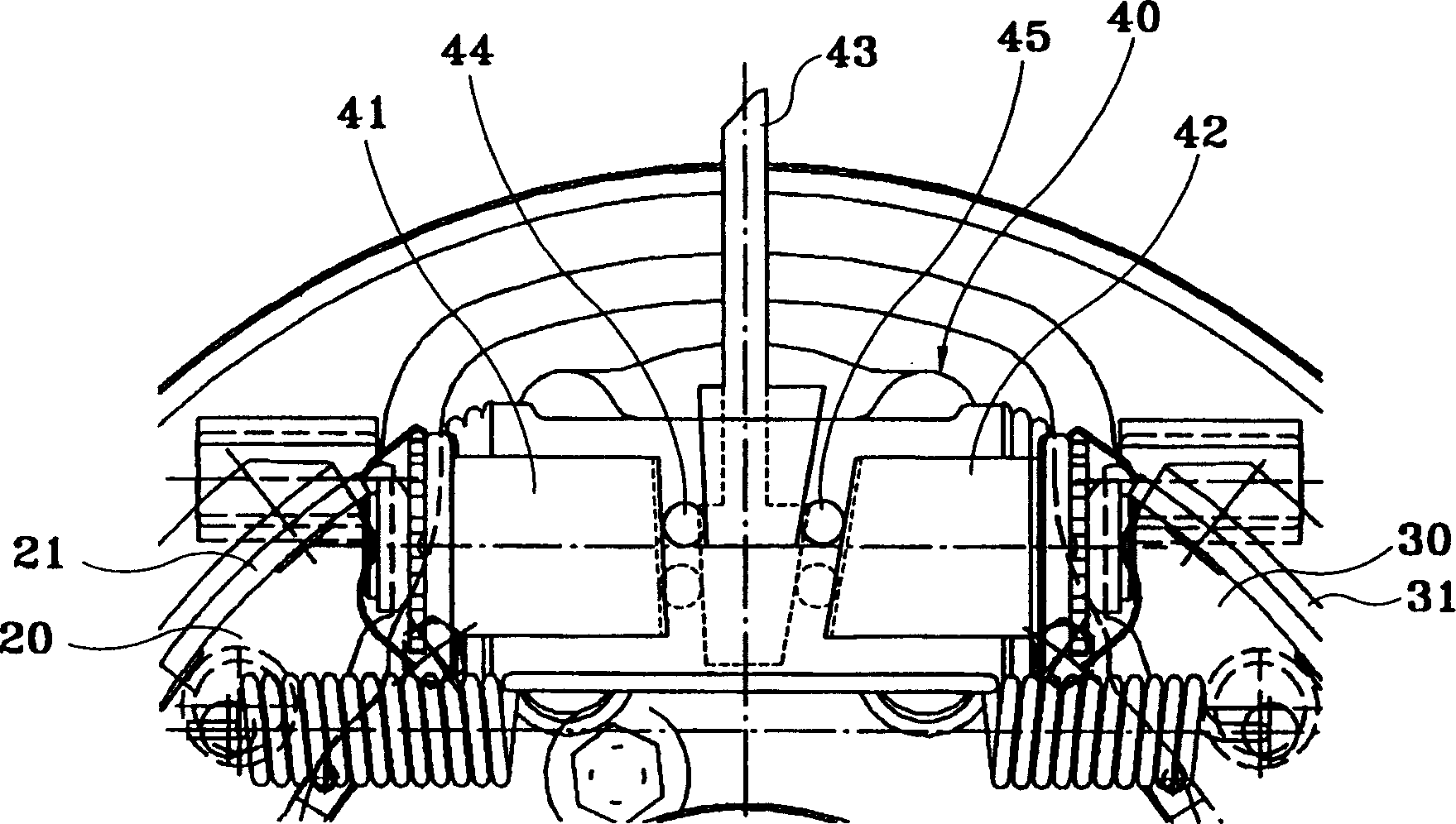
[0021] Such as Figure 4 As shown, the inclination angles θ1 and θ2 with respect to the axis of the wedge 43 are made θ1<θ2, and the inclination angles of the end faces of the two pistons 41 and 42 are also different to correspond to the inclination angle of the wedge 43 .
[0022] Balls 44 and 45 are placed between wedge 43 and pistons 41 , 42 as in conventional techniques.
[0023] As mentioned above, in the conventional method, the forces F1 and F2 of the pistons 41 and 42 are respectively: F1=F / 2*tanθ1, F2=F / 2*tanθ2, therefore, if θ1<θ2, then F1
[0024] That is to say, if the inclination angle becomes larger, the thrust force of the pistons also becomes larger. Therefore, the thrust force of the piston 42 associated with the slave shoe 30 is greater than ...
PUM
 Abstract
Description
Claims
Application Information