RFID tag housing structure, RFID tag installation structure and RFID tag communication method

An installation structure, radio frequency identification technology, applied to record carriers used by machines, cooperating devices, antenna supports/installation devices, etc., can solve the problems of low strength and insufficient protection of RFID tags

Inactive Publication Date: 2003-09-17
HANEX CO LTD
View PDF2 Cites 35 Cited by
  • Summary
  • Abstract
  • Description
  • Claims
  • Application Information

AI Technical Summary

Problems solved by technology

[0013] However, due to the relatively low strength of non-conductive materials such as plastic, it is often not enough to protect RFID tags
For example, in the case where RFID tags are placed on metal manhole covers, etc., issues arise regarding the durability of RFID tags as they are continuously subjected to the weight of passing vehicular traffic, etc.

Method used


Image

  • RFID tag housing structure, RFID tag installation structure and RFID tag communication method
  • RFID tag housing structure, RFID tag installation structure and RFID tag communication method
  • RFID tag housing structure, RFID tag installation structure and RFID tag communication method

Examples


Embodiment Construction

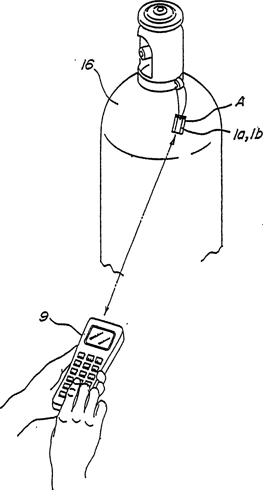
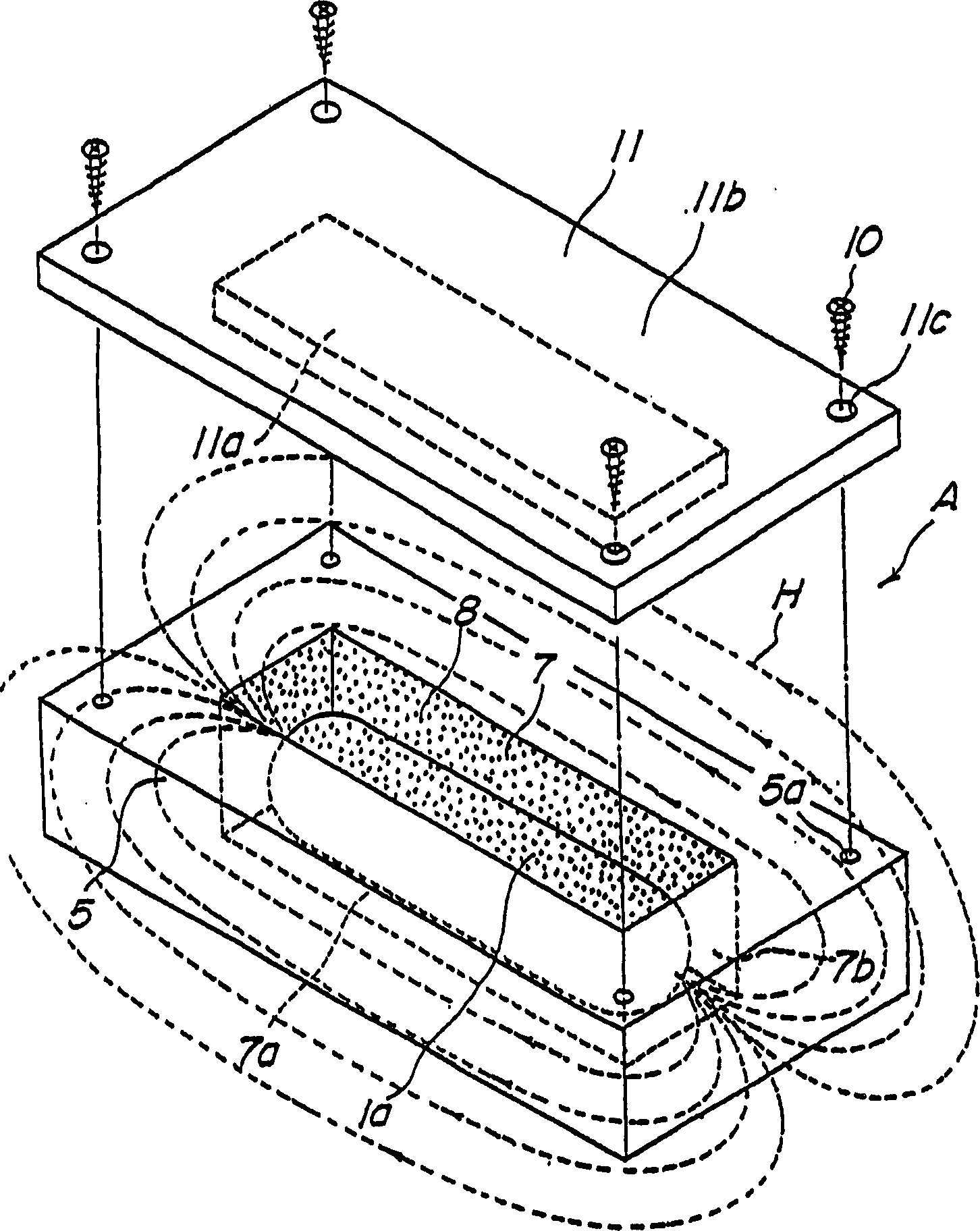
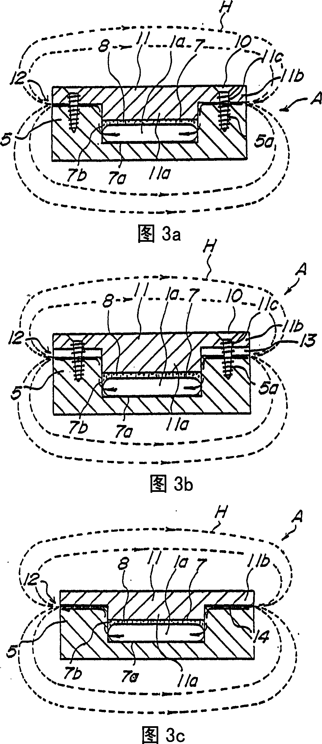
[0102] Embodiments of the accommodating structure, the mounting structure and the communication method of the RFID tag of the present invention will be described in detail with reference to the accompanying drawings. Figures 1 to 1 1B is a schematic diagram illustrating a housing structure, an installation structure and a communication method of an RFID tag housed in a container made of a conductive material having a cylindrical antenna coil; Figures 12 to 1 6B is a schematic diagram illustrating a housing structure, mounting structure and communication method of an RFID tag having a communication dish antenna coil housed in a similar manner.

[0103] First, refer to Figures 1 to 1 1B, illustrating the housing structure, mounting structure and communication method of an RFID tag housed in a container made of conductive material having a cylindrical antenna coil.

[0104] It should be noted that the RFID tags 1a and 1b preferably applicable to the embodiments described belo...


PUM


Abstract

A first object of the present invention is to provide a new installation structure of RFID tags which can effectively protect the RFID tags from external pressure or impact and communicate with the outside during storage, transportation and use. The second object of the present invention is to provide a new mounting structure of an RFID tag even though the RFID tag is mounted on a conductive part such as a metal part and its surface is generally made of metal having excellent strength and durability The protective part cover is also able to communicate with the outside. A third object of the present invention is to provide a communication method using an RFID tag surrounded by a conductive member usually made of metal. Even if the RFID tag is housed in a container generally made of a conductive material such as metal having a large mechanical strength, if a magnetic flux leakage path 12 consisting only of, for example, a gap is formed in this container A, the RFID tag can leak magnetic flux. Communicates with external read / write terminal 9 as a medium.

Description

[0001] The entire disclosure of Japanese Patent Application No.2000-218443 filed on July 19, 2000; and Japanese Patent Application No.2000-233888 filed on August 2, 2000, including specification, claims, drawings and the abstract of the publication are incorporated in their entirety to claim priority under 35 U.S. C119. technical field [0002] The present invention relates to a housing structure, an installation structure and an installation method of an RFID having an antenna coil and a control part. Background technique [0003] Conventional RFID (Radio Frequency Identification) tags are broadly classified into electromagnetic induction type and electromagnetic coupling type; two types of RFID tags are designed to communicate with read / write terminals in a non-contact manner or using electromagnetic waves. [0004] The RDIF tag has an antenna coil and a control section, wherein the signal transmitted from the read / write terminal is received by the antenna coil, converted ...

Claims


Application Information

Patent Timeline
Patent Type & Authority Applications(China)
IPC IPC(8): G06K7/08G06K19/04G06K19/077H01Q1/22H01Q1/42H01Q7/00
CPCG06K7/10336G06K19/041G06K19/07728G06K19/07749G06K19/07758G06K19/07771G06K19/07777H01Q1/2225H01Q1/42H01Q7/00G06K17/00
Inventor 仙波不二夫兵头仲麻吕藤井润内山知树木田茂
Owner HANEX CO LTD
Why Eureka
Try Eureka