Dry-type spiral vacuum pump

A vacuum pump and screw technology, applied in the field of dry screw vacuum pump, can solve the problems of reducing the performance of the vacuum pump, increasing the gap leakage, prone to failure, etc., to eliminate the accident of rotor contact, prevent exhaust pollution, and suppress exhaust temperature. Elevated effect

Inactive Publication Date: 2003-10-01
TAIKO KIKAI IND CO LTD JP
View PDF0 Cites 5 Cited by
  • Summary
  • Abstract
  • Description
  • Claims
  • Application Information

AI Technical Summary

Problems solved by technology

If a one-way valve is installed, this valve is prone to failure, and the process gas that is easy to be mixed with foreign matter is not suitable for the vacuum pump.
[0004] The method of controlling the rotor gap (enlarging the gap) to prevent the sticking phenomenon will increase the leakage of the gap and greatly reduce the performance of the vacuum pump: to find the optimal gap value, it is necessary to make a decision after a large number of repeated experiments

Method used


Image

  • Dry-type spiral vacuum pump
  • Dry-type spiral vacuum pump
  • Dry-type spiral vacuum pump

Examples


Embodiment Construction

[0024] Embodiments of the present invention will be described with reference to the drawings.

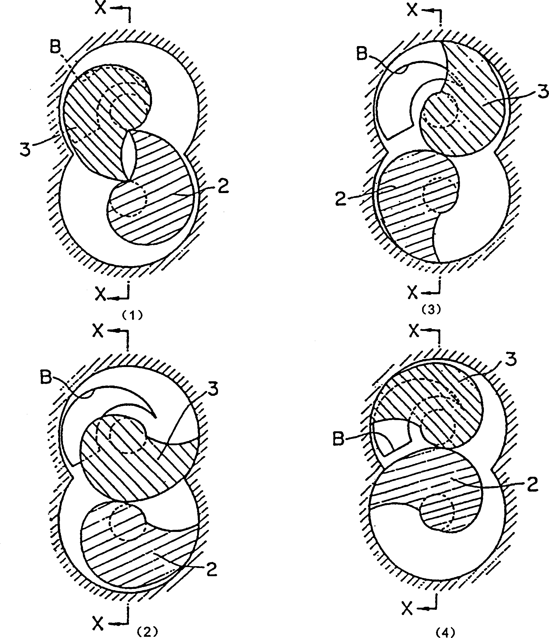
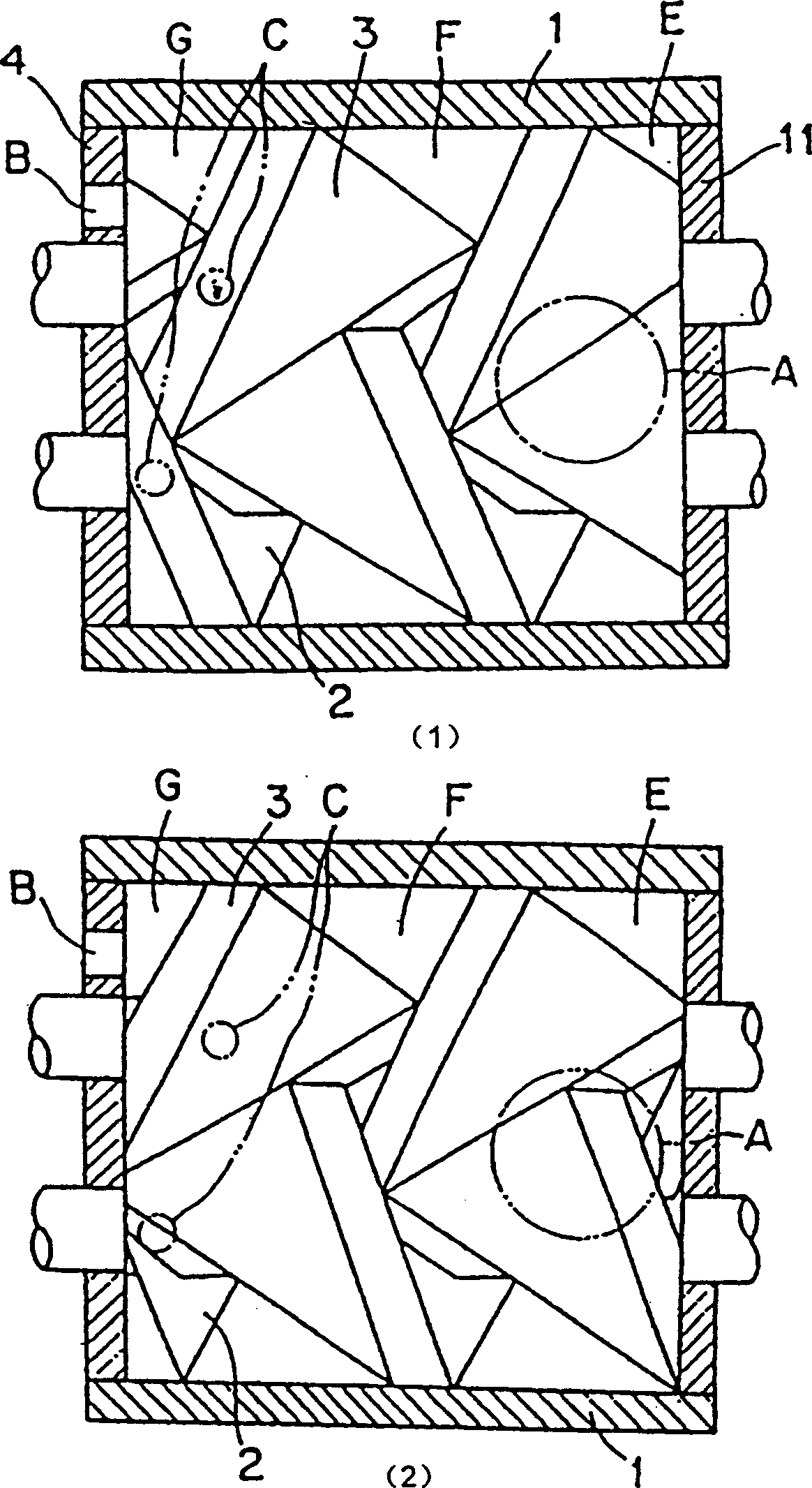
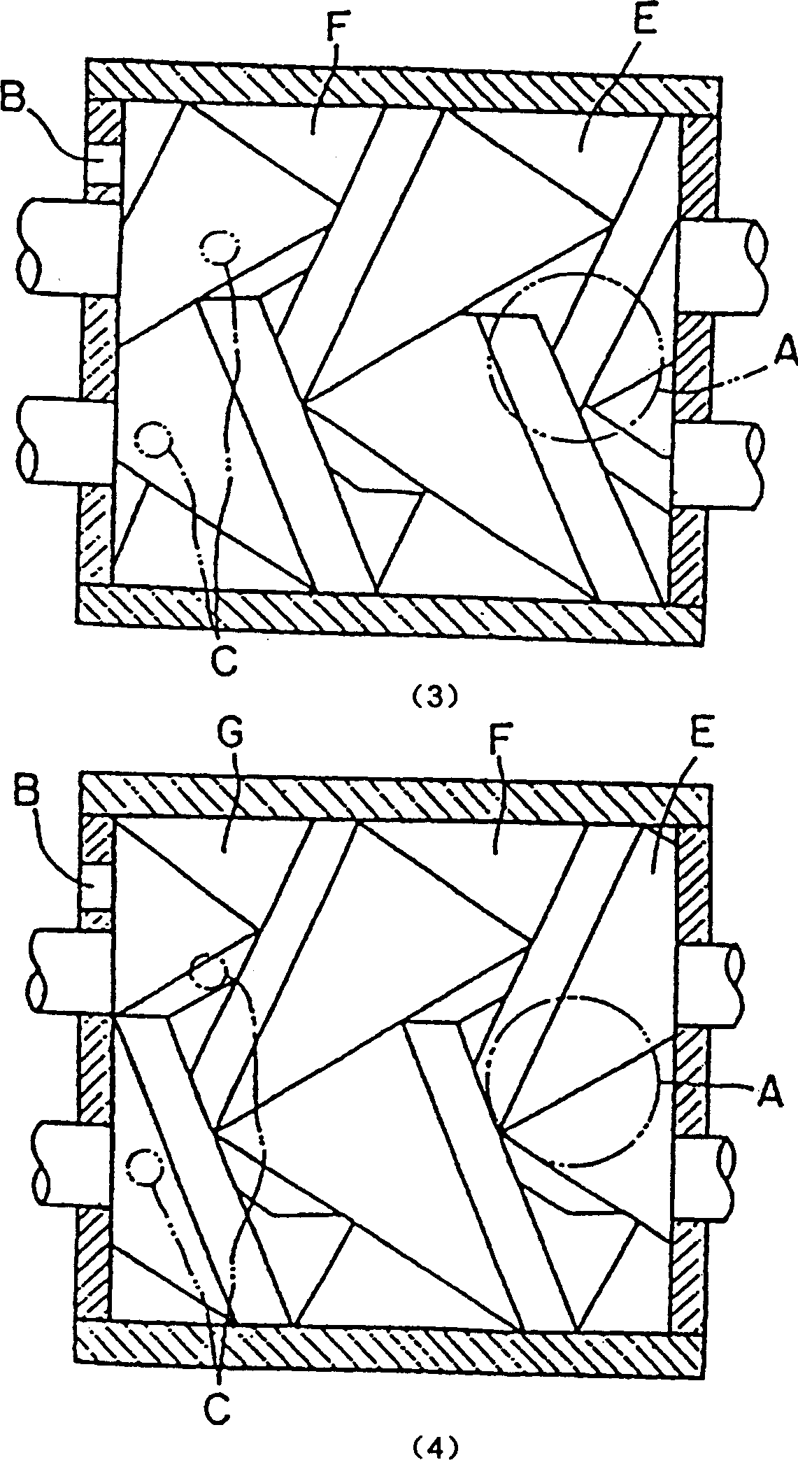
[0025] Fig. 3 shows a helical screw vacuum pump, the pump body 1 contains rotors 2, 3 with right helical patterns and left helical patterns.

[0026] Reference numeral 4 is a side box A containing the space of the above-mentioned threaded portion and constituting a partition wall on the discharge side.

[0027] Bearing bracket 5 is contained on the side case A (4), and bearing bracket 5 is equipped with bearing 6 for supporting the rotating shafts 2a and 3a of the discharge sides of rotors 2 and 3, and a shaft seal 7 for sealing shafts 2a and 3a.

[0028] Motor support 8 is housed on the left side end face of side box A (4). Reference numeral 9 denotes a motor shaft, which transmits the rotational driving force to the rotor 2 via a shaft joint 10 .

[0029] The right end surface of the pump body 1 is equipped with a side box B (11) that accommodates the space for the spiral parts ...


PUM


Abstract

A dry spiral vacuum pump without environmental pollution is disclosed. Its rotor (spiral thread) has a pair of left and right spiral thread whose teeth shape is composed of quimby, quasi-Archimedes curve and arc curve. Its number of leads is more than 2. The internal space of pump is divided into more than 2 oil-dosing chambers. When rotor is rotating, the oil-closing chamber moves from suction side to discharging side. On the side wall of pump body has a air suction hole which is communicated with the second oil-clasing chamber from the discharging side. The position of said suction hole most ensure the longest open time of the second oil-closing chamber for introducing cold air to cool and discharging dust.

Description

technical field [0001] The present invention relates to the invention of a dry screw vacuum pump. The rotor of this kind of pump, viewed from the cross-section at right angles to the shaft, has a right-hand helical pattern, a left A pair of helical patterns, separated by the inner wall of the pump and the spiral sealing line to form a closed oil chamber, introducing cold air into the closed oil chamber to cool the rotor, in a single-stage state up to a high compression ratio, for vacuum compression, and in a vacuum state It can discharge the dust that tends to remain in the suction gas in the pump casing. Background technique [0002] Conventional screw vacuum pumps perform high-pressure compression in a single-stage state, which will generate a lot of compression heat, and it is difficult to maintain a gap between the outer circle of the screw rotor or the thread and the inner wall of the pump, causing a sticking accident; therefore, from the suction side Liquid is injecte...

Claims


Application Information

Patent Timeline
Patent Type & Authority Applications(China)
IPC IPC(8): F04C18/16F04C25/02
Inventor 吉村将士
Owner TAIKO KIKAI IND CO LTD JP
Why Eureka
Try Eureka