
Air conditioner

An air-conditioning device and cooling water circulation technology, applied in air-conditioning systems, space heating and ventilation, heating methods, etc., can solve problems such as temperature rise of cooling water

Inactive Publication Date: 2003-10-01
SANYO ELECTRIC CO LTD +1
View PDF0 Cites 4 Cited by
  • Summary
  • Abstract
  • Description
  • Claims
  • Application Information

AI Technical Summary

Problems solved by technology

[0004] However, there is currently no efficient detection device for cooling water leakage, so there are problems such as abnormal rise in cooling water temperature due to insufficient cooling water

Method used


Image

  • Air conditioner
  • Air conditioner
  • Air conditioner

Examples


Embodiment Construction

[0013] Hereinafter, embodiments of the present invention will be described with reference to the accompanying drawings.

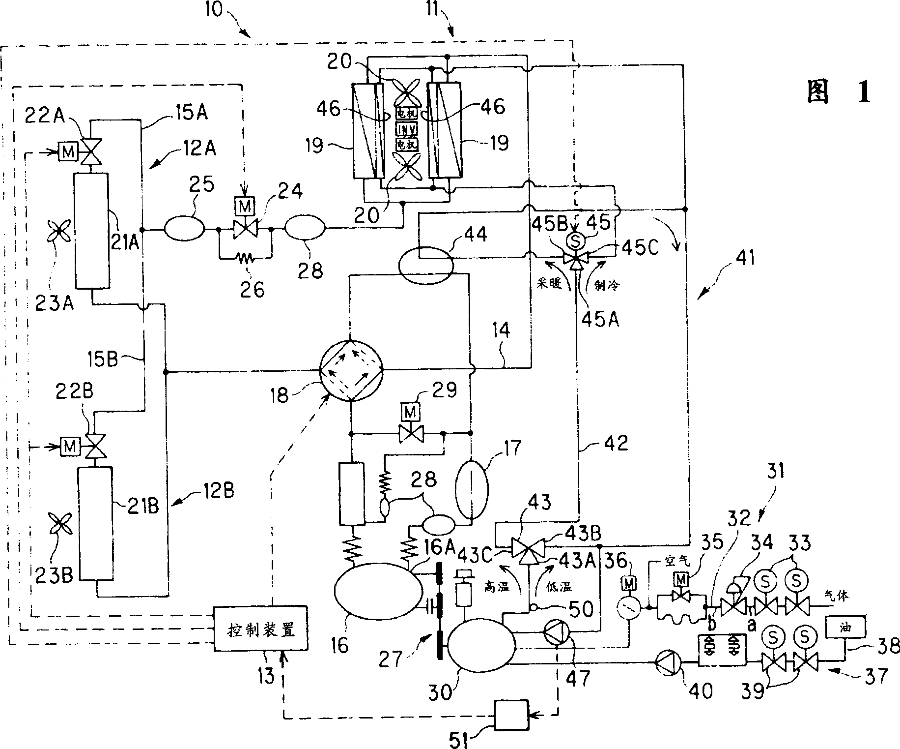
[0014] FIG. 1 is a circuit diagram showing a refrigerant circuit and the like in an embodiment of the air conditioner of the present invention.

[0015] As shown in FIG. 1 , a heat pump air conditioner 10 as a refrigerating apparatus includes an outdoor unit 11, a plurality of (for example, two) indoor units 12A and 12B, a control device 13, an outdoor refrigerant piping 14 of the outdoor unit 11, and an indoor unit. The respective indoor refrigerant pipes 15A and 15B of 12A and 12B are connected together.

[0016] The outdoor unit 11 is installed outdoors, a compressor 16 is arranged on the outdoor refrigerant piping 14, a heat accumulator 17 is arranged on the suction side of the compressor 16, and a four-way valve 18 is arranged on the discharge side, on the side of the four-way valve 18. The outdoor heat exchanger 19, the outdoor expansion valve 24, an...


PUM


Abstract

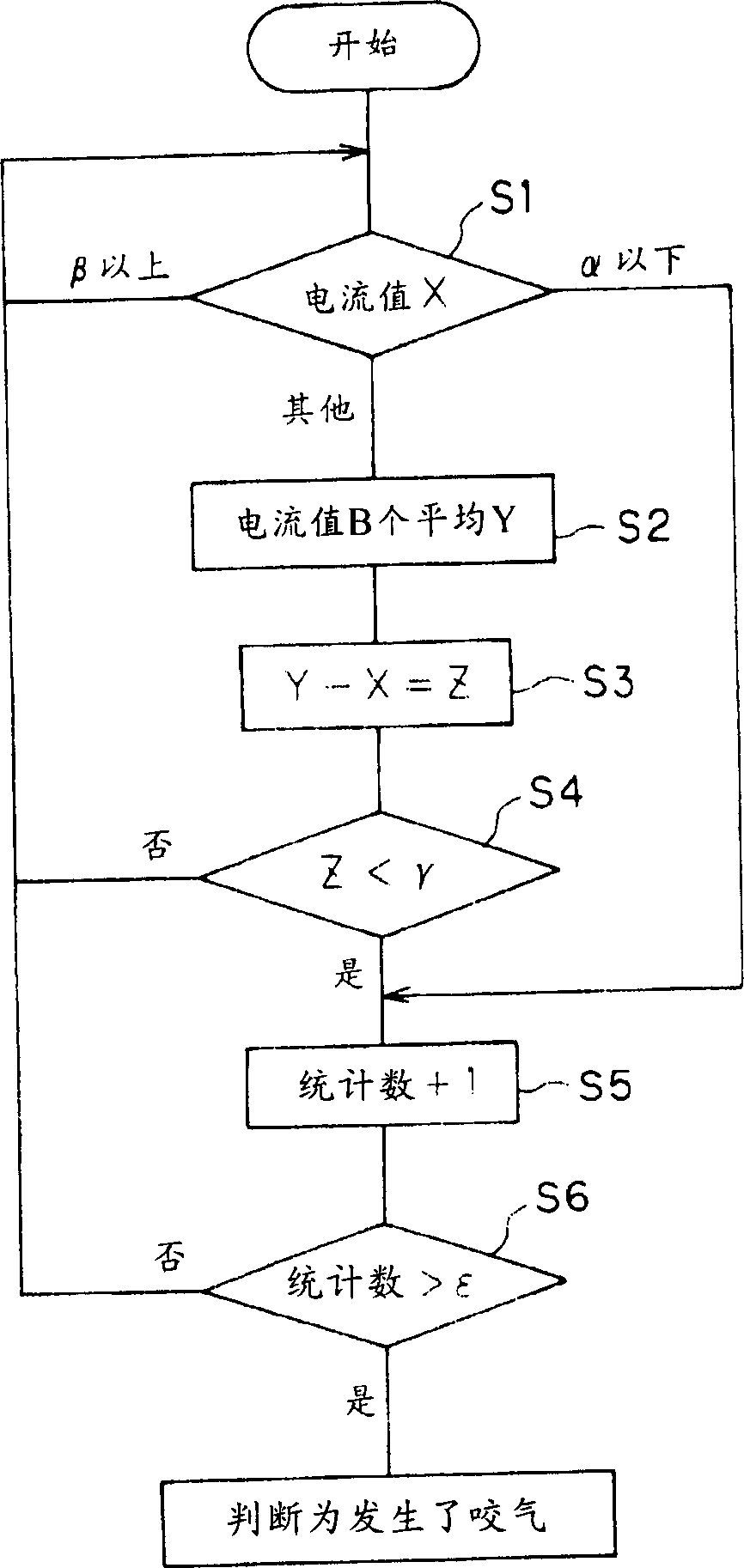
An air conditioning device capable of detecting cooling water leakage in an engine cooling device with high efficiency. In this air conditioning device, the compressor 16 installed on the outdoor unit is driven by the engine 30, and has an engine cooling device that uses a cooling water circulation pump to circulate and cool the cooling water of the engine in the radiator, including detecting the cooling water circulation pump 47. A driving current detection unit 51 and a determination unit 13 that determines the occurrence of bite in the cooling water circulation pump 47 based on the detection value.

Description

technical field [0001] The present invention relates to an air conditioner having an engine cooling device for cooling an engine driving a compressor. Background technique [0002] Generally, the compressor mounted on the outdoor unit of the air conditioner is driven by the engine, and the air conditioner has an engine cooling device that circulates and cools the cooling water of the engine in the radiator by using a cooling water circulation pump. familiar. [0003] Since such an engine cooling device is constructed by connecting water pipes, there is a possibility that cooling water leaks at each connection. [0004] However, at present, there is no device for efficiently detecting the leakage of the cooling water, so there are problems such as abnormal rise in the temperature of the cooling water due to insufficient cooling water. [0005] Therefore, an object of the present invention is to solve the above-mentioned problems in the prior art, and to provide an air condi...

Claims


Application Information

Patent Timeline
IPC IPC(8): F01P11/18F24F3/06F24F5/00F24F11/02F25B27/00
CPCY02A30/274
Inventor 滨田弘毅
Owner SANYO ELECTRIC CO LTD
Learn More